


TM1637 Digital Clock with Time Setup & Alarm – Arduino Nano Prototype
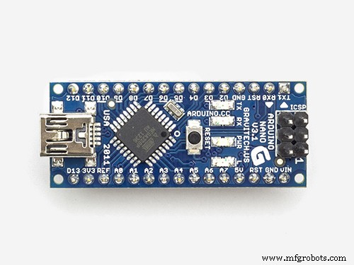
Components and supplies
 |
| × | 1 | |||
| × | 1 | ||||
| × | 1 | ||||
 |
| × | 1 | |||
 |
| × | 1 |
About this project
This is a prototype of the time and alarm setup mechanism which I am planning to use in my next digital clock projects.I hope you find it useful.If you think of any improvements please let me know. I would be more then glad to look into them and potentially incorporate in my code.
You can watch the whole tutorial on
If you like this content and you want to support me in clreating similar videos go to my Patreon webpage
https://www.patreon.com/MariosIdeas
Or
https://www.paypal.com/cgi-bin/webscr?cmd=_s-xclick&hosted_button_id=7PD67JWZ9S3EJ&source=url
Code
- Displaying time from RTC module plus time setup and Alarm setup functionality
Displaying time from RTC module plus time setup and Alarm setup functionalityArduino
This code is reading current time from the RTC module. Then it also allows to update current time and also setup Alarm time.Setup actions are performed using 3 buttons.
// Mario's Ideas
// TM1637 Digital Clock with Setup and Alarm Functionality

#include <Arduino.h>
#include <TM1637Display.h>
#include <virtuabotixRTC.h> //

// RTC module declaration
// PINS CLK, DAT, RST
virtuabotixRTC myRTC(A1,A2,A3);

// Variables to store previous values read off RTC module
int minutes;
int hours;
// Variables to store the time at which Alarm should go off
int Alarm_minutes=05;
int Alarm_hours=18;
uint8_t Blank[] = {0x0};

int POSITION=0;

//Table to store 4 digits, used in time and Alarm setup procedure
int digits[3];

int interval=0;

#define Alarm 9 // Button to switch alarm mode on or off
#define Buzer 13
#define Led 8


//Statuses
boolean Alarm_set=false;
boolean Alarm_in_progress=false;
boolean Setup_on= false;

// 4digit display connection pins (Digital Pins)
#define CLK 4
#define DIO 5


// 4 digit display declaration
TM1637Display clock(CLK, DIO);

void setup() {

 attachInterrupt(digitalPinToInterrupt(2), Press_A_Button,RISING);
 attachInterrupt(digitalPinToInterrupt(3), Press_B_Button,RISING);
 pinMode(Alarm, INPUT);
 pinMode(Buzer, OUTPUT);
 pinMode(Led, OUTPUT);
 digitalWrite(Buzer,LOW);
 clock.setBrightness(0x0f);
 Serial.begin(9600);
}

void Press_A_Button(){
  if (interval>3){
    if (Setup_on==false){
      Setup_on=true;
      if (Alarm_set==true){
        digits[0]= (int)Alarm_hours/10;
        digits[1]= Alarm_hours-((int)Alarm_hours/10)*10;
        digits[2]= (int)Alarm_minutes/10;
        digits[3]= Alarm_minutes-((int)Alarm_minutes/10)*10;
      }
      else {
        digits[0]= (int)myRTC.hours/10;
        digits[1]= myRTC.hours-((int)myRTC.hours/10)*10;
        digits[2]= (int)myRTC.minutes/10;
        digits[3]= myRTC.minutes-((int)myRTC.minutes/10)*10;
      }
    }
    else{
      POSITION++;
      if (POSITION==4){
        if (Alarm_set==true){
          Alarm_minutes=digits[3]+digits[2]*10;
          Alarm_hours=digits[1]+digits[0]*10;
        }
        else {
          myRTC.setDS1302Time( 0, digits[3]+digits[2]*10, digits[1]+digits[0]*10,myRTC.dayofweek, myRTC.dayofmonth, myRTC.month, myRTC.year);
          clock.showNumberDec(digits[0],false,1,0);
          clock.showNumberDec(digits[1],false,1,1);
          clock.showNumberDec(digits[2],false,1,2);
         clock.showNumberDec(digits[3],false,1,3);
        }
        POSITION=0;
        Setup_on=false;
      }
    }
  }
  interval=0;
}

void Press_B_Button(){
  if (interval>3){
    if(Setup_on){
      digits[POSITION]=digits[POSITION]+1;
      if (POSITION==0 and digits[POSITION]==3) digits[POSITION]=0;
      if (POSITION!=0 and digits[POSITION]==10) digits[POSITION]=0;
      interval=0;
    }
  }
  interval=0;
}

void loop() {
  if (digitalRead(Alarm)==HIGH and Alarm_set==false ){
    if (interval>30){
      digitalWrite(Led,HIGH);
      Alarm_set=true;
      delay(300);
    }
  } else{
    if (digitalRead(Alarm)==HIGH and Alarm_set==true){
      if (interval>30){
      Alarm_set=false;
      Alarm_in_progress=false;
      digitalWrite(Led,LOW);
      delay(300);
    }
   }
 }
 myRTC.updateTime();


 if (Setup_on==true){
    clock.showNumberDec(digits[0],false,1,0);
    clock.showNumberDec(digits[1],false,1,1);
    clock.showNumberDec(digits[2],false,1,2);
    clock.showNumberDec(digits[3],false,1,3);
    delay(200);
    clock.setSegments(Blank, 1,POSITION);
    delay(200);
    clock.showNumberDec(digits[0],false,1,0);
    clock.showNumberDec(digits[1],false,1,1);
    clock.showNumberDec(digits[2],false,1,2);
    clock.showNumberDec(digits[3],false,1,3);
  }
 else{
   if (myRTC.minutes==Alarm_minutes and myRTC.hours==Alarm_hours and Alarm_set==true and Setup_on==false){
    Alarm_in_progress=true;
   }

   if (Alarm_in_progress){
     digitalWrite(Buzer,HIGH);
     delay(1000);
     digitalWrite(Buzer,LOW);
     delay(1000);
   }

 if (myRTC.minutes!=minutes){

   clock.showNumberDecEx((int)myRTC.hours/10*1000+(myRTC.hours-((int)myRTC.hours/10)*10)*100+ (int)myRTC.minutes/10*10+myRTC.minutes-((int)myRTC.minutes/10)*10, (0x80 >> 1), true);

   minutes=myRTC.minutes;
   hours=myRTC.hours;

   }
 }
 if (interval<200) interval++;
}
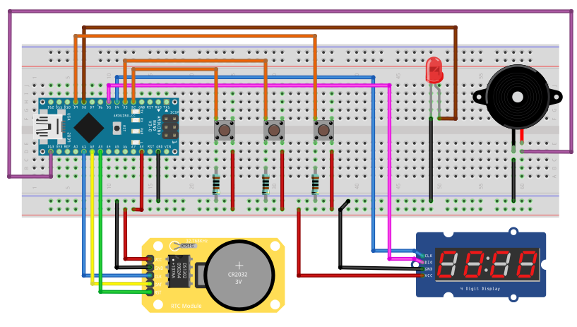
Schematics
Arduino-Based Nunchuk-Operated 6-DoF Robotic Arm Kit
Smart Wireless Light Switch Controller: Arduino‑Based Remote Switch Manipulator
Manufacturing process
- Precision Word Clock: Minute‑Level Time Display in Words
- Arduino Temperature Monitor & Real-Time Clock Using a 3.2” TFT Display
- Build a Berlin Clock with Arduino UNO – DIY LED Matrix Clock
- Real-Time Arduino Weather Clock: OLED Display for Time, Date & Temperature
- Arduino Ultrasonic Distance & Temperature Monitor with LCD Alarm System
- Multi-Display LCD Alarm Clock with Customizable Faces
- 128x64 LCD Smart Clock with Analog/Digital Time & Temperature – Arduino Nano + DS3231 RTC
- Build a Reliable Alarm Clock with DS1302 RTC and Arduino UNO
- Reliable Arduino UNO Digital Clock: Simple, Accurate, and Easy to Build
- Mastering Arduino with DS3231 RTC: Step‑by‑Step Tutorial