


Rocky Rover: Build a Robotic Vision System with PixyCam and Arduino 101
Components and supplies
 |
| × | 1 | |||
| × | 1 | ||||
| × | 1 | ||||
 |
| × | 1 | |||
 |
| × | 1 | |||
| × | 1 | ||||
| × | 4 | ||||
| × | 1 | ||||
 |
| × | 1 | |||
| × | 1 | ||||
| × | 1 | ||||
| × | 1 |
Apps and online services
 |
| |||
 |
|
About this project
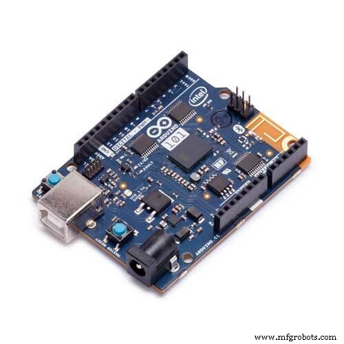
Intel Arduino 101 based Rover with PixyCam!Hackster Live events are awesome! Intel sponsored our Hackster Dallas event and sent us some Intel Arduino 101 to build Rovers. Thanks Intel, thanks Arduino. Here's the Rover I built for the event.
I built this device following this tutorial from Johnathan Hottell. He created some videos to build the BLE Rover. And it's is easy to follow! Check it out here. Here's the video from Johnathan Hottell.
I have the Rover with 4 motors so I followed this.
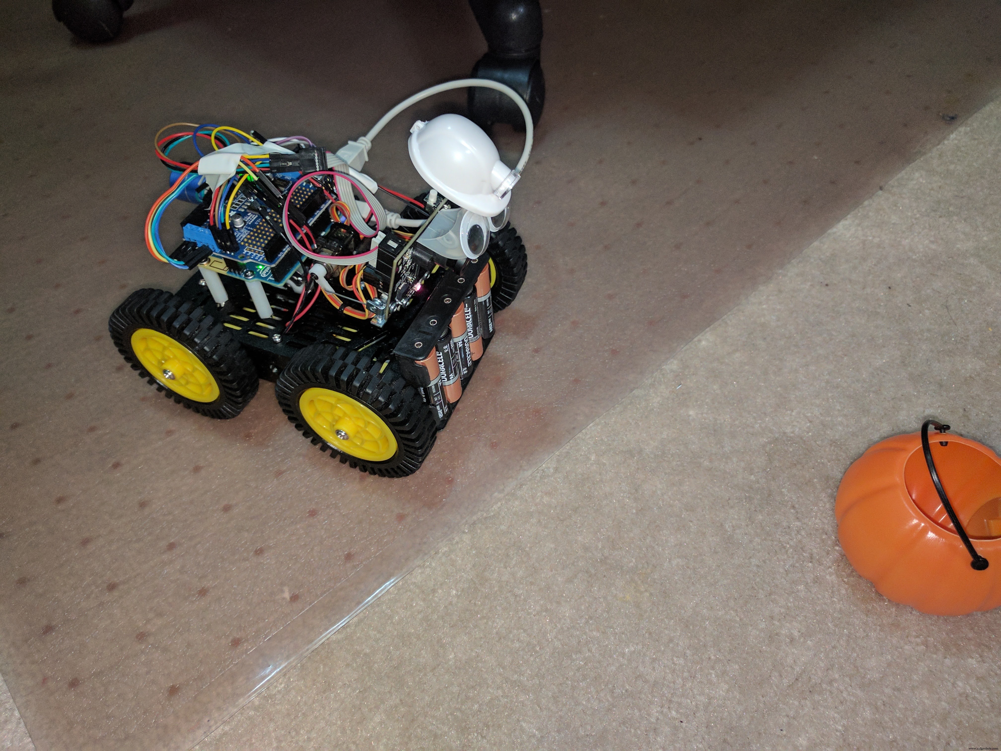
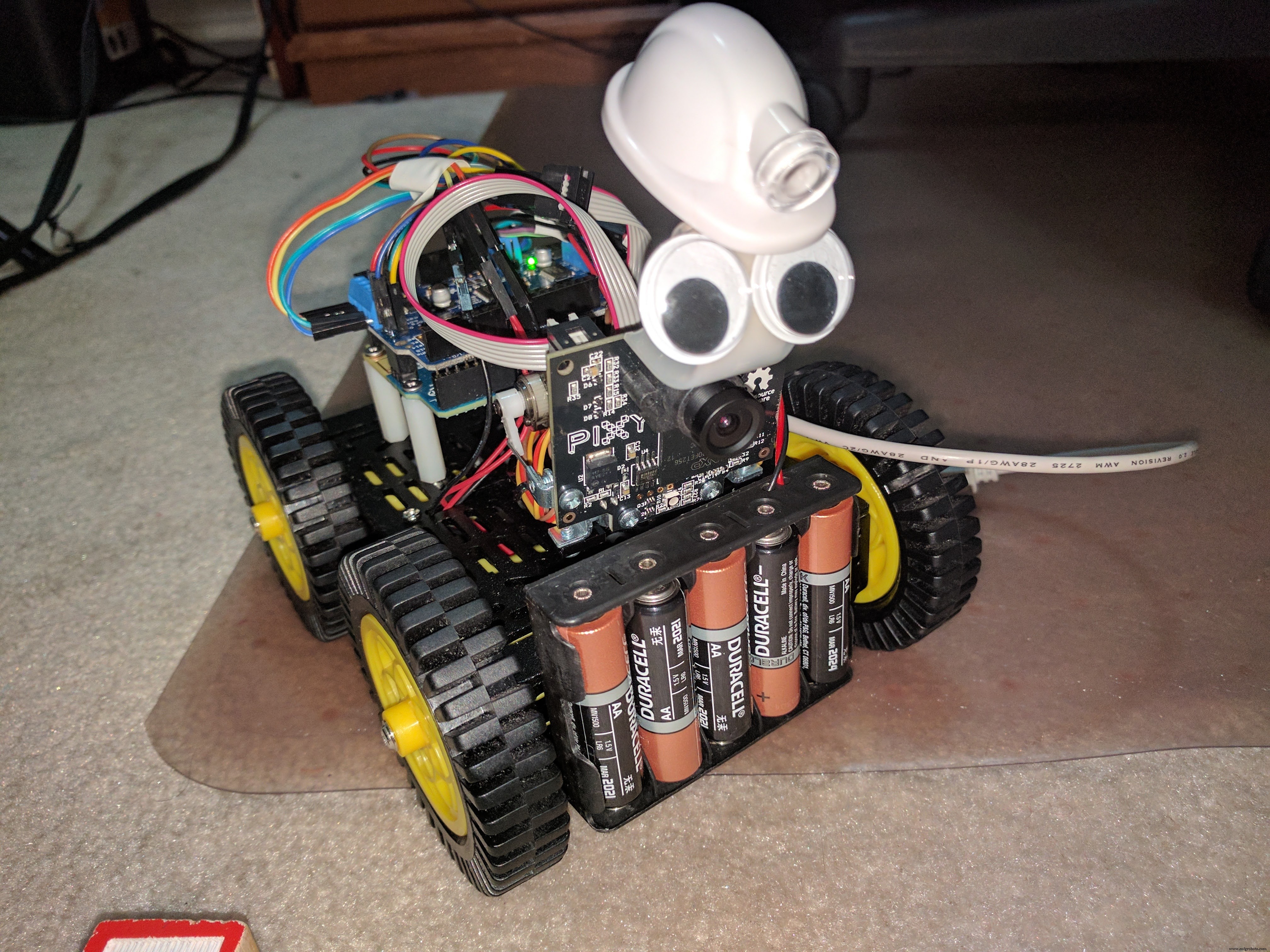
After building the Rover, and getting it connected with Blynk. I decided to improve the build and add a PixyCam. I moved the battery holder in front so I can mount a pan/tilt camera.
PixyCamPixyCam makes Robotic vision made easy. Pixy is a fast vision sensor for DIY robotics, it is easy to teach Pixy an object just by pressing a button. It’s capable of tracking hundreds of objects simultaneously and only provides the data that it's tracking.
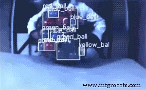
I decided to track an Orange Pumpkin.
I'm surprised how easy it is to get it going. Here's the link for the instructions for connecting PixyCam to Arduino. Click here for the assembly instructions for Pan/Tilt mechanism. I'm glad that it has a lot of pictures, very easy to follow. I followed the setup and build instructions, how to integrate with Arduino. I tested their examples.
Here's what I found out about the API.
PixyCam Arduino APIUsing Pixy with Arduino is really simple. You simply include the SPI and Pixy headers:
#include <SPI.h>
#include <Pixy.h>
And make a global instance of Pixy by putting this little guy outside your setup()
and loop()
functions:
Pixy pixy;
The most important method in the Arduino library is getBlocks()
, which returns the number of objects Pixy has detected. You can then look in the pixy.blocks[]
array for information about each detected object (one array member for each detected object.) Each array member (i
) contains the following fields:
pixy.blocks[i].signatureThe signature number of the detected object (1-7 for normal signatures)
pixy.blocks[i].xThe x location of the center of the detected object (0 to 319)
pixy.blocks[i].yThe y location of the center of the detected object (0 to 199)
pixy.blocks[i].widthThe width of the detected object (1 to 320)
pixy.blocks[i].heightThe height of the detected object (1 to 200)
pixy.blocks[i].angleThe angle of the object detected object if the detected object is a color code.
pixy.blocks[i].print()A member function that prints the detected object information to the serial port
So it's simple to talk to Pixy with your Arduino! For more information on the Arduino Library and API, go here. Here's the code used for the Rover. I modified the original BLE code and added object tracking. During setup:
void setup()
{
 .....
 pixy.init();
 ....
}
Main loop looks something like this:
void loop()
{
 ......
 // read pixy data and get blocks
 static int i = 0;
 int j;
 uint16_t blocks;
 char buf[32];
 int32_t panError, tiltError;
 blocks = pixy.getBlocks();
 //if there are blocks
 if (blocks)
 {

   panError = X_CENTER-pixy.blocks[0].x;
   tiltError = pixy.blocks[0].y-Y_CENTER;

   panLoop.updatePan(panError);
   tiltLoop.update(tiltError);

   pixy.setServos(panLoop.m_pos, tiltLoop.m_pos);
   i++;

   // frame would bog down the Arduino
   if (i%10==0)
   {
     int trackedBlock = 0;
     sprintf(buf, "Detected %d:\n", blocks);
     Serial.print(buf);

     long maxSize = 0;
     for (j=0; j<blocks; j++)
     {
       sprintf(buf, "  block %d: ", j);
       Serial.print(buf);
       pixy.blocks[j].print();

       long newSize = pixy.blocks[j].height * pixy.blocks[j].width;
       if (newSize > maxSize)
       {
         trackedBlock = j;
         maxSize = newSize;
       }
     }
     int32_t followError = RCS_CENTER_POS - panLoop.m_pos;
      // Size is the area of the object.
     // We keep a running average of the last 8.
     size += pixy.blocks[trackedBlock].width * pixy.blocks[trackedBlock].height;
     size -= size >> 3;

     int forwardSpeed = constrain(400 - (size/256), -100, 400);

     int32_t differential = (followError + (followError * forwardSpeed))>>8;

     int leftSpeed = constrain(forwardSpeed + differential, -400, 400);
     int rightSpeed = constrain(forwardSpeed - differential, -400, 400);

     motor1->setSpeed(leftSpeed); //left
     motor3->setSpeed(leftSpeed);
     motor2->setSpeed(rightSpeed); //left
     motor4->setSpeed(rightSpeed);
     double width = pixy.blocks[trackedBlock].width;

       if (width <= 5)
       {
       } else

        if (width < 20 && !running)
       {
          Serial.println("running");
          motor1->run(FORWARD);
          motor3->run(FORWARD);
          motor2->run(FORWARD);
          motor4->run(FORWARD);
          running = true;
       }

       else if (width > 80 && !running)
       {
          Serial.println("running");
          motor1->run(BACKWARD);
          motor3->run(BACKWARD);
          motor2->run(BACKWARD);
          motor4->run(BACKWARD);
          running = true;
       }

       else if (width >= 20 && width <= 80 && running) {
         motor1->setSpeed(128);
         motor2->setSpeed(128);
         motor3->setSpeed(128);
         motor4->setSpeed(128);
         motor2->run(RELEASE);
         motor4->run(RELEASE);
         motor1->run(RELEASE);
         motor3->run(RELEASE);
         running = false;
       }
   }
 }
}
In order to run the Blynk without the PixyCam controlling it, put the lens cap on. It will make sure that PixyCam won't interfere controlling the bot. If this project made you interested in programming in Arduino or using PixyCam in your next project, please click the "Respect Project" button and follow me.
Feel free to ask questions.
Code
Rocky Rover
Manufacturing process
- Arduino POV Clock: Build a Persistance‑of‑Vision LED Display
- SERENA: A Custom Arduino Mega 2560 Alarm System with TFT LCD Touchscreen
- Build a Functional Arduino-Powered 3D‑Printed Robotic Arm – Step‑by‑Step Guide
- Optimized Power Solutions for Arduino Projects
- Arduino 101 BLE + Blynk: DIY Bluetooth‑Controlled Tank Robot
- Build a Portable Persistence of Vision Display with Arduino UNO and ATtiny85
- DIY Arduino Smartwatch: Build Your Own Apple Watch‑Style Timepiece
- Smart Basement Ventilation System: Arduino‑Powered Moisture Control
- Arduino 101: Build a Pedometer with DHT11 Sensor & LCD Display
- Advanced Smart Waste Monitoring with Arduino 101: BLE & WiFi Integration