


Smartphone G‑Sensor Controlled Robot Car with Arduino and Bluetooth
Components and supplies
 |
| × | 1 | |||
| × | 1 | ||||
| × | 1 | ||||
| × | 1 |
Apps and online services
|
About this project
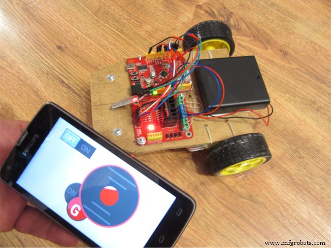
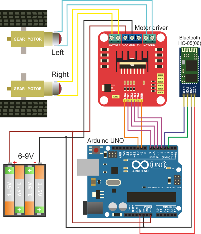
Build robotcar using any available platform built on two-wheel circuit. Connection diagram of electronic components is shown in the figure below. You will need Arduino UNO or compliant board, Bluetooth HC-05 (06) module, motor driver, and power supply battery. Gear motors are placed on the platform and force to move robot wheels.

Step 2.
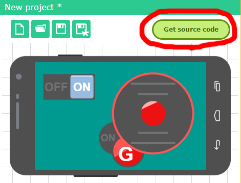
Go to RemoteXY service website on http://remotexy.com/en/editor/ and create a graphical user interface to control the robot. Set a control feature using the G-sensor for joystick. An example of interface is in the figure below. Click the button "Get source code".
Download the source code of GUI and open it in Arduino IDE. For compilation you need RemoteXY.h library; the library can be downloaded from the link http://remotexy.com/en/library/ . You can already try to load code in Arduino and connect with mobile application. But while this is only the code blank, then you will need to add required functionality linking a graphical interface and motor driver.
Step 4.Then you need to add robot control functionality to the source code using a graphical interface. For this purpose the field RemoteXY structure. RemoteXY structure displays all of your GUI controls.
The resulting source code is shown below. You can compile it and upload it to Arduino.
Step 5.Install a mobile application RemoteXY on http://remotexy.com/en/download/ . When the application is running on a mobile device, press Bluetooth button connection in the list, select the name of your Bluetooth module, for HC-05 (06) modules the name typically will be INVOR or HC-06.
It works!
Code
- Remote control robot car via RemoteXY mobile app
Remote control robot car via RemoteXY mobile appC/C++
You can download the RemoteXY.h library by link http://remotexy.com/en/library//////////////////////////////////////////////
// RemoteXY include library //
/////////////////////////////////////////////
/* RemoteXY select connection mode and include library */
#define REMOTEXY_MODE__SOFTWARESERIAL
#include <SoftwareSerial.h>
#include <RemoteXY.h>
/* RemoteXY connection settings */
#define REMOTEXY_SERIAL_RX 2
#define REMOTEXY_SERIAL_TX 3
#define REMOTEXY_SERIAL_SPEED 9600
/* RemoteXY configurate */
unsigned char RemoteXY_CONF[] =
{ 3,0,23,0,1,5,5,15,41,11
,43,43,1,2,0,6,5,27,11,5
,79,78,0,79,70,70,0 };
/* this structure defines all the variables of your control interface */
struct {
/* input variable */
signed char joystick_1_x; /* =-100..100 x-coordinate joystick position */
signed char joystick_1_y; /* =-100..100 y-coordinate joystick position */
unsigned char switch_1; /* =1 if switch ON and =0 if OFF */
/* other variable */
unsigned char connect_flag; /* =1 if wire connected, else =0 */
} RemoteXY;
/////////////////////////////////////////////
// END RemoteXY include //
/////////////////////////////////////////////
/* defined the right motor control pins */
#define PIN_MOTOR_RIGHT_UP 7
#define PIN_MOTOR_RIGHT_DN 6
#define PIN_MOTOR_RIGHT_SPEED 10
/* defined the left motor control pins */
#define PIN_MOTOR_LEFT_UP 5
#define PIN_MOTOR_LEFT_DN 4
#define PIN_MOTOR_LEFT_SPEED 9
/* defined the LED pin */
#define PIN_LED 13
/* defined two arrays with a list of pins for each motor */
unsigned char RightMotor[3] =
{PIN_MOTOR_RIGHT_UP, PIN_MOTOR_RIGHT_DN, PIN_MOTOR_RIGHT_SPEED};
unsigned char LeftMotor[3] =
{PIN_MOTOR_LEFT_UP, PIN_MOTOR_LEFT_DN, PIN_MOTOR_LEFT_SPEED};
/*
speed control of the motor
motor - pointer to an array of pins
v - motor speed can be set from -100 to 100
*/
void Wheel (unsigned char * motor, int v)
{
if (v>100) v=100;
if (v<-100) v=-100;
if (v>0) {
digitalWrite(motor[0], HIGH);
digitalWrite(motor[1], LOW);
analogWrite(motor[2], v*2.55);
}
else if (v<0) {
digitalWrite(motor[0], LOW);
digitalWrite(motor[1], HIGH);
analogWrite(motor[2], (-v)*2.55);
}
else {
digitalWrite(motor[0], LOW);
digitalWrite(motor[1], LOW);
analogWrite(motor[2], 0);
}
}
void setup()
{
/* initialization pins */
pinMode (PIN_MOTOR_RIGHT_UP, OUTPUT);
pinMode (PIN_MOTOR_RIGHT_DN, OUTPUT);
pinMode (PIN_MOTOR_LEFT_UP, OUTPUT);
pinMode (PIN_MOTOR_LEFT_DN, OUTPUT);
pinMode (PIN_LED, OUTPUT);
/* initialization module RemoteXY */
RemoteXY_Init ();
}
void loop()
{
/* event handler module RemoteXY */
RemoteXY_Handler ();
/* manage LED pin */
digitalWrite (PIN_LED, (RemoteXY.switch_1==0)?LOW:HIGH);
/* manage the right motor */
Wheel (RightMotor, RemoteXY.joystick_1_y - RemoteXY.joystick_1_x);
/* manage the left motor */
Wheel (LeftMotor, RemoteXY.joystick_1_y + RemoteXY.joystick_1_x);
}
Schematics
Manufacturing process
- Build a DTMF Decoder Using Only an Arduino – No Extra ICs Needed
- Build a Smart Voltmeter with Arduino & Smartphone – Easy DIY Project
- Build an Android‑Controlled Remote Vehicle with Raspberry Pi Motor Shield
- MobBob: Build Your Own Arduino Robot, Controlled Seamlessly via Android Smartphone
- Capacitive Touch LED Switch with Arduino UNO – Easy DIY Project
- DIY Arduino USB Trackpad: Convert an Old Laptop Pad into a Modern Input Device
- Build a 4-Wheel Arduino Robot Controlled via Dabble App
- Arduino Web-Driven XY Plotter with Stepper Motor Controller
- Smartphone‑Controlled Bluetooth Mouse: Build Your Own Virtual Joystick
- Build a Morse Code Transmitter with Arduino – Easy DIY Guide