


Build a DTMF Decoder Using Only an Arduino – No Extra ICs Needed
Components and supplies
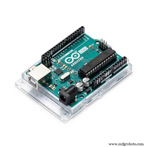 |
| × | 1 | |||
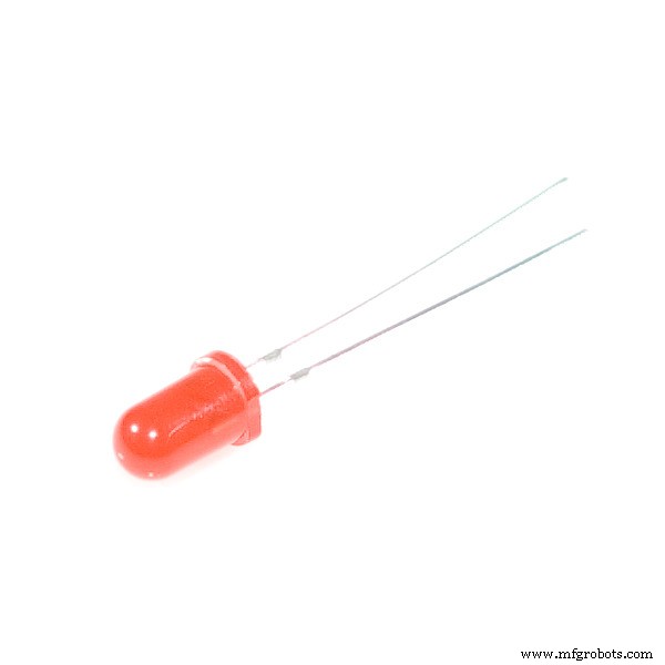 |
| × | 10 | |||
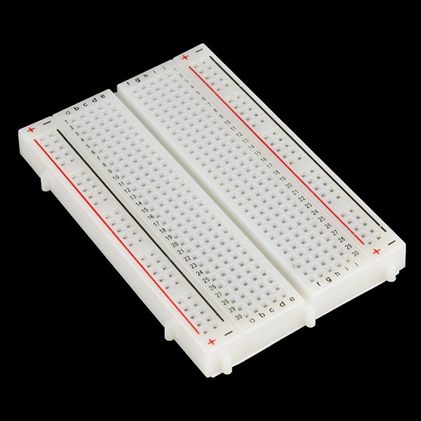 |
| × | 1 | |||
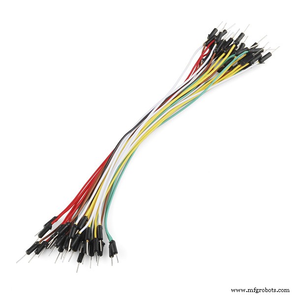 |
| × | 20 |
Apps and online services
 |
|
About this project
As I was going through my semester project list with the choices to choose I saw a DTMF-controlled car that used the CM 8870 IC as a DTMF decoder and the encoded binary data was given to Arduino to perform the left right and forward back operations. The DTMF decoder function, the main part, used an external IC that I found difficult to integrate and was in search for a code or a library that could even replace the IC in the circuit with some additional code and couldn't find a satisfying solution. But one library based upon Goertzel algorithm (Goertzel.h) that could tell if a specific frequency was present in the tone or not by calculating number of pulses per unit time and their amplitude contribution in the given tone signal.
I used the basic example code as the base and have written a code that can detect the present dominant DTMF frequencies in the tone and can decode that to give us the number that was pressed on the other side during the phone call.
Code
- Arduino Code DTMF decoder
Arduino Code DTMF decoderArduino
compile and upload the code in Arduino IDE and dont forget to add the library first.the link for the library is :
https://github.com/jacobrosenthal/Goertzel
/*

 This code is a basic implementation of a DTMF decoder for detecting the 16 character
 DTMF code from the analog pin A0 and gives the decoded output by checking for all the
 Upper and lower tones in the DTMF matrix and gives us the corresponding number by turning
 on the corresponding digital bit for the numbers 0-9 and by Serially printing the rest of
 the characters.
  This work is entirely based on the Kevin Banks code found at
  http://www.embedded.com/design/embedded/4024443/The-Goertzel-Algorithm
  so full credit to him for his generic implementation and breakdown.
  The Goertzel algorithm is long standing so see
  http://en.wikipedia.org/wiki/Goertzel_algorithm for a full description.
  It is often used in DTMF tone detection as an alternative to the Fast
  Fourier Transform because it is quick with low overheard because it
  is only searching for a single frequency rather than showing the
  occurrence of all frequencies.
  * THIS CODE IS Made/modified by "Mian Mohammad Shoaib" and  Released into the public domain.
  * for any querries related to the code feel free to ask at

  MMSHOAIB8452@GMAIL.COM
 */


#include <Goertzel.h>

int sensorPin = A0;
const int N = 100;                       //it is the number of samples code will take y0u can change for sensitivity and can if large it can slow the arduino
const float threshold = 2000;            //minimum tone amplitude to be considered we can change it for more senstivity
const float sampling_freq = 8900;        //maximum detectable frequency is the sampling rate/2 and arduino uno with 16Mhz can support sampling upto 8900 Hz
float x_frequencies[4];                  // make two arrays for holding x and y axis frequencies to be detected
float y_frequencies[4];

void setup(){
 pinMode(13, OUTPUT);                    //initalize blink led to show if any tone is detected
 pinMode(2, OUTPUT);                     //initialize 10 pins as output to show the dtmf outputs from 2 to number 12 rest will be just derially printed to the monitor
 pinMode(3, OUTPUT);
 pinMode(4, OUTPUT);
 pinMode(5, OUTPUT);
 pinMode(6, OUTPUT);
 pinMode(7, OUTPUT);
 pinMode(8, OUTPUT);
 pinMode(9, OUTPUT);
 pinMode(10, OUTPUT);
 pinMode(11, OUTPUT);
 pinMode(12, OUTPUT);

  Serial.begin(9600);

x_frequencies[0]=1209;                //just initialize the arrays with the x and y axis tone frequencies along with their row and colon number
x_frequencies[1]=1336;
x_frequencies[2]=1477;
x_frequencies[3]=1633;

y_frequencies[0]=697;
y_frequencies[1]=770;
y_frequencies[2]=852;
y_frequencies[3]=941;
}

bool detect_tone(float freq){

Goertzel goertzel = Goertzel(freq, N, sampling_freq);        //initialize library function with the given sampling frequency no of samples and target freq
  goertzel.sample(sensorPin);                               //Will take n samples
  float magnitude = goertzel.detect();                      //check them for target_freq

 if(magnitude>threshold){                                   //if you're getting false hits or no hits adjust the threshold
  digitalWrite(13,HIGH);                                    //blink led on 13 if a pulse is detected
  delay(250);
  digitalWrite(13,LOW);
  Serial.print(freq);
  Serial.print("\n");
  return true;
 }
  else
    return false;
}


void print_number(int row,int column){
int number=0;
if(row==0){                                             //find the number corresponding to the found row and column
  if(column== 0)
  number= 1;
  else if(column== 1)
  number= 2;
  else if(column== 2)
  number= 3;
  else if(column== 3)
  number= 10;
}
else if(row==1){
  if(column== 0)
  number= 4;
  else if(column== 1)
  number= 5;
  else if(column== 2)
  number= 6;
  else if(column== 3)
  number= 11;
}
else if(row==2){
  if(column== 0)
  number= 7;
  else if(column== 1)
  number= 8;
  else if(column== 2)
  number= 9;
  else if(column== 3)
  number= 12;
}
else if(row==3){
  if(column== 0)
  number= 14;
  else if(column== 1)
  number= 0;
  else if(column== 2)
  number= 15;
  else if(column== 3)
  number= 13;
}

if(number <10){
digitalWrite((number+2),HIGH);
Serial.print(number);
}
else if(number ==10)
Serial.print('A');
else if(number ==11)
Serial.print('B');
else if(number ==12)
Serial.print('C');
else if(number ==13)
Serial.print('D');
else if(number ==14)
Serial.print('*');
else if(number ==15)
Serial.print('#');
Serial.print("\n");
delay(800);
for(int i=2;i<=12;i++){
  digitalWrite(i,LOW);
}
}

void loop(){
int column=0,row=0;
int i=0;
while(1){
  if(detect_tone(x_frequencies[i]) == true){
    column = i;
    break;
  }
  i++;
if(i==4)
i=0;
}

i=0;
while(1){
if(detect_tone(y_frequencies[i]) == true){
    row = i;
    break;
  }
   i++;
if(i==4)
i=0;
}
print_number(row,column);

}
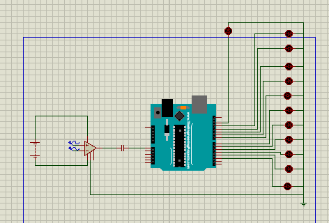
Schematics
The circuit uses 10 LEDs connected from digital pin 2 to 12 that will turn on when any tone for the numbers between 0-9 is pressed respectively and a pulse detection LED will be connected on the pin 13 which will give a short blink when a pulse or a signal is detected, numbers greater than 9 (the special characters) will be displayed via Serial printing in the IDE.The input pin from the audio jack or the AUX cable will be connected to the analog pin A0 with a 1uF capacitor in series that will filter out the low frequencies and the DC offset.
Manufacturing process
- SERENA: A Custom Arduino Mega 2560 Alarm System with TFT LCD Touchscreen
- Python 3 to Arduino UNO: Easy Command Control and LED Demo
- Build a Compact FM Radio with Arduino Nano and RDA8057M
- Arduino Web-Driven XY Plotter with Stepper Motor Controller
- Build a Real-Time Face-Tracking System with Arduino & OpenCV
- Smartphone G‑Sensor Controlled Robot Car with Arduino and Bluetooth
- Efficiently Control 10 Buttons with a Single Interrupt on Arduino UNO
- Build a Precise Clock with Arduino Nano and 16x2 LCD
- Build a Morse Code Transmitter with Arduino – Easy DIY Guide
- Arduino-Based MIDI Stepper Motor Synthesizer