


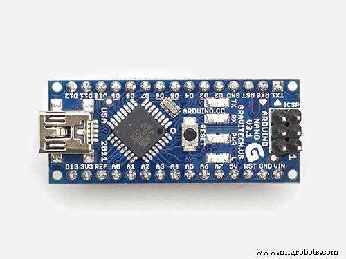
Accurate Timekeeping: Sync DS3231 RTC with GPS on Arduino Nano
Components and supplies
 |
| × | 1 | |||
| × | 1 | ||||
| × | 1 | ||||
| × | 1 | ||||
| × | 1 | ||||
| × | 1 | ||||
| × | 2 | ||||
| × | 2 | ||||
| × | 1 | ||||
| × | 1 | ||||
| × | 1 | ||||
| × | 1 | ||||
| × | 2 | ||||
| × | 1 |
About this project
My DS3231 drifts, I was doing the normal thing in updating it by compiling some code using system time, but this proved a bit inaccurate as the compiling and uploading kept getting interrupted by other processes happening on my computer.
After I found that GPS gave out accurate time (UTC) and date I decided to use that to set my DS3231.
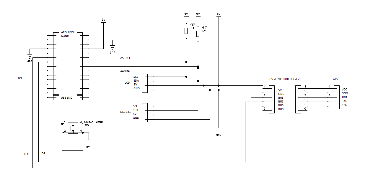
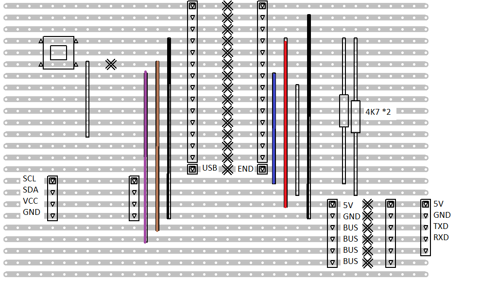
Circuit:LCD backpack to Arduino:
GND - GND
VCC - 5V
SDA - SDA (A4)
SCL - SCL (A5)
DS3231 clock module to Arduino:
GND - GND
VCC - 5V
SDA - SDA (A4)
SCL - SCL (A5)
LEVEL SHIFTER from Arduino:
5V - 5V
GND - GND
D3 - BUS
D4 - BUS
NEO 6M GPS from level shifter:
3V - VCC
GND - GND
BUS - TXD (ends up at D3)
BUS - RXD (ends up at D4)
SWITCH CONTACTS:
SWITCH - D9
SWITCH - GND
Power:I supply the power to my circuit through the USB cable.
Software:The 99% of the software is the parsing.ino example in the Adafruit GPS library. I added in a small amount of code to pass the extracted GPS date and time to the DS3231 and some additional code to display the time form the DS3231 on an LCD display.
Library’s used:Adafruit GPSLibrary by Adafruit version 1.0.3
RTCLib by Adafruit version 1.2.0
NewLiquidCrystalfor the I2C display backpack.
Operation:Turn the unit on.
The LCD will display the date and time values currently in the DS3231 registers.
Wait a while for the GPS to lock.
Press the button to set the time via the GPS signal.
The LCD will display the new time.
Operation limitations:The GPS unit does take time to lock and there is no indicator that lock has been achieved.Pressing the set button without lock resulted in my DS3231 date being set to2000:0:0 and the time to 0:0:0.
After the red LED on the GPS unit starts to blink seems to be the best time to press the set button – this can be into 10’s of minutes (indoors).
Initially the DS3231 unit I used had a flat battery, on pressing set the date was set to2000:0:0 and the time to 0:164:164. It took quite a while for the battery to get enough charge to accept the GPS data and continue ticking away correctly on its own.
GPS quirks:The board I purchased said simply NEO 6M GPS and has the connecting pins marked with their functions. I took a look at the datasheet for the device [1] and that stated the device functioned on around 3V, hence my use of a level shifter. However on closer inspection I found a 4A2D chip soldered to the board, an internet search shows it to be a voltage regulator but this does not guarantee that the communication lines are level shifted (my unit came with no circuit diagram).
I have also read on line that different GPS modules vary in their ability to receive a good signal indoors, hence my addition of an LCD display so I could take it outside.
LCD quirk:I am using one of the oddball ones that have an I2C address of 0x3F, most use the address 0x27, so if you see nothing try altering that first.
Library quirk:The libraryRTCLib (Adafruit version 1.2.0) sets the time and date registers but not the day register of the DS3231. The library has a function to return the day of the week which is calculated on the fly using the values in the date register.
I found this odd but realized eventually that it makes sense, setting the day register would require that your code be set up to alter it on leap years while generating the day by a formula avoids this.
UTC & Local time:I did a search on UTC and found that no change was required for my local time, so if you need it you will have to add in that bit of code yourself.
References:[1] https://www.u-blox.com/sites/default/files/products/documents/NEO-6_DataSheet_(GPS.G6-HW-09005).pdf(retrieved /Dec/2018)
Code
- Set DS3231 code file
Set DS3231 code fileArduino
// Date and time functions using a DS3231 RTC connected via I2C and Wire lib
#include <Wire.h>
#include "RTClib.h"//Aadafruit version 1.2.0 on my machine

RTC_DS3231 RTC;

char daysOfTheWeek[7][12] = {"Sunday", "Monday", "Tuesday", "Wednesday", "Thursday", "Friday", "Saturday"};
const int days_string_length =12;

//end of clock stuff

//for lcd display
//#include <Wire.h>//has already been included (above)
// Get the LCD I2C Library here:
// https://bitbucket.org/fmalpartida/new-liquidcrystal/downloads
#include <LiquidCrystal_I2C.h>
//Note the unusual address of 0x3F most lcd's use address of 0x27 so if you see nothing try altering that first
LiquidCrystal_I2C lcd(0x3F, 2, 1, 0, 4, 5, 6, 7, 3, POSITIVE);  // Set the LCD I2C address
//end of for lcd display

//for button
#define button 9

// Test code for Adafruit GPS modules using MTK3329/MTK3339 driver
//
// This code shows how to listen to the GPS module in an interrupt
// which allows the program to have more 'freedom' - just parse
// when a new NMEA sentence is available! Then access data when
// desired.
//
// Tested and works great with the Adafruit Ultimate GPS module
// using MTK33x9 chipset
//    ------> http://www.adafruit.com/products/746
// Pick one up today at the Adafruit electronics shop
// and help support open source hardware & software! -ada

#include <Adafruit_GPS.h>
#include <SoftwareSerial.h>

// If you're using a GPS module:
// Connect the GPS Power pin to 5V
// Connect the GPS Ground pin to ground
// If using software serial (sketch example default):
//   Connect the GPS TX (transmit) pin to Digital 3
//   Connect the GPS RX (receive) pin to Digital 2
// If using hardware serial (e.g. Arduino Mega):
//   Connect the GPS TX (transmit) pin to Arduino RX1, RX2 or RX3
//   Connect the GPS RX (receive) pin to matching TX1, TX2 or TX3

// If you're using the Adafruit GPS shield, change
// SoftwareSerial mySerial(3, 2); -> SoftwareSerial mySerial(8, 7);
// and make sure the switch is set to SoftSerial

// If using software serial, keep this line enabled
// (you can change the pin numbers to match your wiring):
SoftwareSerial mySerial(3, 2);

// If using hardware serial (e.g. Arduino Mega), comment out the
// above SoftwareSerial line, and enable this line instead
// (you can change the Serial number to match your wiring):

//HardwareSerial mySerial = Serial1;


Adafruit_GPS GPS(&mySerial);


// Set GPSECHO to 'false' to turn off echoing the GPS data to the Serial console
// Set to 'true' if you want to debug and listen to the raw GPS sentences.
#define GPSECHO  false //--------->turned off

// this keeps track of whether we're using the interrupt
// off by default!
boolean usingInterrupt = false;
void useInterrupt(boolean); // Func prototype keeps Arduino 0023 happy

void setup()
{

  // connect at 115200 so we can read the GPS fast enough and echo without dropping chars
  // also spit it out
  Serial.begin(115200);
  Serial.println("Adafruit GPS library basic test!");

  // 9600 NMEA is the default baud rate for Adafruit MTK GPS's- some use 4800
  GPS.begin(9600);

  // uncomment this line to turn on RMC (recommended minimum) and GGA (fix data) including altitude
  GPS.sendCommand(PMTK_SET_NMEA_OUTPUT_RMCGGA);
  // uncomment this line to turn on only the "minimum recommended" data
  //GPS.sendCommand(PMTK_SET_NMEA_OUTPUT_RMCONLY);
  // For parsing data, we don't suggest using anything but either RMC only or RMC+GGA since
  // the parser doesn't care about other sentences at this time

  // Set the update rate
  GPS.sendCommand(PMTK_SET_NMEA_UPDATE_1HZ);   // 1 Hz update rate
  // For the parsing code to work nicely and have time to sort thru the data, and
  // print it out we don't suggest using anything higher than 1 Hz

  // Request updates on antenna status, comment out to keep quiet
  GPS.sendCommand(PGCMD_ANTENNA);

  // the nice thing about this code is you can have a timer0 interrupt go off
  // every 1 millisecond, and read data from the GPS for you. that makes the
  // loop code a heck of a lot easier!
  useInterrupt(true);

  delay(1000);
  // Ask for firmware version
  mySerial.println(PMTK_Q_RELEASE);


  //start lcd
  lcd.begin(16,2);
  lcd.backlight();
  lcd.clear();

  //setup button
  pinMode(button,INPUT_PULLUP);


}


// Interrupt is called once a millisecond, looks for any new GPS data, and stores it
SIGNAL(TIMER0_COMPA_vect) {
  char c = GPS.read();
  // if you want to debug, this is a good time to do it!
#ifdef UDR0
  if (GPSECHO)
    if (c) UDR0 = c;
    // writing direct to UDR0 is much much faster than Serial.print
    // but only one character can be written at a time.
#endif
}

void useInterrupt(boolean v) {
  if (v) {
    // Timer0 is already used for millis() - we'll just interrupt somewhere
    // in the middle and call the "Compare A" function above
    OCR0A = 0xAF;
    TIMSK0 |= _BV(OCIE0A);
    usingInterrupt = true;
  } else {
    // do not call the interrupt function COMPA anymore
    TIMSK0 &= ~_BV(OCIE0A);
    usingInterrupt = false;
  }
}

uint32_t timer = millis();
void loop()                     // run over and over again
{
  // in case you are not using the interrupt above, you'll
  // need to 'hand query' the GPS, not suggested :(
  if (! usingInterrupt) {
    // read data from the GPS in the 'main loop'
    char c = GPS.read();
    // if you want to debug, this is a good time to do it!
    if (GPSECHO)
      if (c) Serial.print(c);
  }

  // if a sentence is received, we can check the checksum, parse it...
  if (GPS.newNMEAreceived()) {
    // a tricky thing here is if we print the NMEA sentence, or data
    // we end up not listening and catching other sentences!
    // so be very wary if using OUTPUT_ALLDATA and trytng to print out data
    //Serial.println(GPS.lastNMEA());   // this also sets the newNMEAreceived() flag to false

    if (!GPS.parse(GPS.lastNMEA()))   // this also sets the newNMEAreceived() flag to false
      return;  // we can fail to parse a sentence in which case we should just wait for another
  }

  // if millis() or timer wraps around, we'll just reset it
  if (timer > millis())  timer = millis();

static bool second_time_round=false;

  // approximately every 2 seconds or so, print out the current stats
  //if (millis() - timer > 2000) {
  //  timer = millis(); // reset the timer

  //Write data to clock if button pressed - button normally held high by internal pullup
  if(!digitalRead(button)){

//Note: RTClib does not explicitly set day of the week register on DS3231.
//Instead when you use dayOfTheWeek() the day is calculated by a formula based on the date.
//Sunday is taken to be zero.
//(based on my reading of the library header and ccp files)

    //set rtc
      RTC.adjust(DateTime(GPS.year, GPS.month, GPS.day, GPS.hour, GPS.minute, GPS.seconds));


      //lcd
      lcd.clear();
      lcd.setCursor(2,0);
      lcd.print("Pressed set");
      delay(5000);
      lcd.clear();

        }

    DateTime now = RTC.now();

    lcd.setCursor(4,0);
    lcd.print(now.year(), DEC);
    lcd.print('/');
    lcd.print(now.month(), DEC);
    lcd.print('/');
    lcd.print(now.day(), DEC);
    lcd.print(' ');
    lcd.setCursor(4,1);
    lcd.print(now.hour(), DEC);
    lcd.print(':');
    lcd.print(now.minute(), DEC);
    lcd.print(':');
    lcd.print(now.second(), DEC);
    lcd.print("          ");

}
Schematics
Manufacturing process
- Set Screws Explained: Design, Differences, and Applications
- Mastering Java’s Set Interface: Concepts, Methods, and Practical Examples
- Mastering Java SortedSet: A Practical Guide to TreeSet and Its Methods
- Leaving a Lasting Legacy: Authentic Leadership for a Better Future
- Java 10 Development Environment Setup: Build, Compile, and Run
- Build a GPS Destination Notifier with Arduino UNO & NEO‑6M Module
- Build a Reliable Arduino Clock with Date, Time, and LCD Display
- Punch Sets Demystified: A Comprehensive Guide
- Linear-Guide CNC Lathes: Precision, Speed, and Light-Duty Production
- Essential Guide to Choosing the Right Mechanic Toolset