


The Evolution, Design, and Manufacturing of Lawn Mowers
Background
The lawn mower is a mechanical device that shaves grass by rotating one or more blades at high speed. While early workers cut lawns with scythes—slow, tiring, and effective only on wet grass—mechanized cutting began with Edwin Budding’s 1830 prototype, inspired by textile shearing machines. Budding’s cylindrical mower, powered by a chain‑driven rear roller, could be drawn by horses or operated by hand. Though the first commercial models were heavy and inefficient, they laid the groundwork for future innovation.
By the late 19th century, steam‑powered and, later, gas‑driven mowers appeared. The Benz Company (Germany) and Coldwell Lawn Mower Company (New York) introduced the first gas‑powered designs in 1897, but mass production began in 1902 with James Edward Ransome’s commercially viable mower featuring a passenger seat. Subsequent refinements—lighter frames, side‑wheel layouts, and self‑propulsion—enabled widespread adoption across Britain and beyond.
Power Mower Variants
Today’s power mowers fall into four primary categories: rotary, power‑reel, riding, and tractor. Rotary mowers dominate the market, accounting for roughly 80% of the 40 million units in use on a typical summer Saturday. They feature a single rotating blade encased in a housing, spinning at up to 3,000 RPM—about 19,000 ft (5,800 m) per minute at the blade tip. The blade’s shape, often horn‑ or wind‑tunnel‑styled, directs cut grass into a discharge chute. Self‑propelled models use a chain or belt to turn the wheels, while push‑style units rely on manual steering. Power‑reel mowers, in contrast, employ multiple fixed blades on a rotating drum. These blades cut along their entire length, offering greater efficiency on dense turf. Though more complex to manufacture, they remain popular for their superior cut quality on certain grass types.
Raw Materials
A typical gas‑powered walk‑behind mower comprises up to 270 parts, including a two‑ or four‑cycle engine, machined metal components, and a few plastic accessories like side discharge chutes and covers. The majority of the structure—mower pan, handlebar, engine, and blades—is fabricated from steel, while plastic elements provide lightweight and corrosion‑resistant solutions.
Manufacturing Process
Producing a conventional rotary mower demands meticulous inventory control, precise part placement, and synchronized labor. Robotic cells often work alongside skilled technicians to ensure quality and efficiency.
Unloading and Distribution
- Components arrive by truck at the plant’s loading dock and are transferred via forklifts or overhead trolleys to stations for forming, machining, painting, or direct assembly.
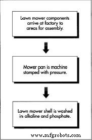
At the factory, parts undergo machine‑stamping, plasma cutting, welding, and electrostatic powder coating. The steel mower pan—heated under intense pressure—receives precise apertures via plasma cutters before being welded to other structural elements and baked for a durable finish.
The Mower Pan
- 1. The pan is stamped, then moved to a robotic cell where plasma cutting creates necessary openings. Plasma—a highly ionized gas—provides clean cuts and can also be used for welding.
- 2. Baffles and other components are welded onto the pan, which is then powder‑painted. The process involves chemical cleaning, electrostatic spraying, and oven curing to achieve a hard, enamel‑like coating that withstands corrosive grass fluids and debris.
- 3. The handlebar is bent, pierced, and assembled with control mechanisms in a robotic cell before final integration.
Handlebar Shaping
- 4. The handlebar undergoes a three‑stage robotic process: bending at multiple points, flattening the ends, and punching holes for the starting mechanism, blade controls, and pan attachment.
Subassembly and Final Assembly
- 5. Key subassemblies—engine, tires, shift mechanisms, wiring harnesses, and bearings—are sourced from specialized suppliers. Injection‑molded plastics supply side discharge chutes and covers.
- 6. Assembly teams assemble major subassemblies on a moving line. The engine is mounted, the mower pan bolted, shift controls installed, and the blade clamped with torque wrenches. After adding wheels and hardware, the unit is flipped onto its wheels, the handlebar attached, and cables routed. Each mower undergoes performance testing before shipment.
Quality Control
Throughout production, inspectors verify fit, seam, tolerance, and finish. Paint quality is critical; samples are subject to ultrasonic testing that simulates 450 hours of environmental exposure. Paint failures are addressed by adjusting coating or cleaning cycles. Final performance tests—engine cranking, RPM verification, and safety switch checks—ensure each mower meets Consumer Product Safety Commission standards, including a blade stop within three seconds of handle release.
The Future
Emerging power sources—such as solar‑powered mowers—promise quieter operation and zero emissions. While current models provide only about two hours of cutting before needing a three‑day recharge, advances in battery technology are rapidly expanding runtime. As storage capacity grows, solar mowers will become a viable, sustainable alternative to gasoline engines.
Manufacturing process
- What is VMC Machining? An Expert Overview of Vertical Machining Centers
- Expert Guide to Aluminum Laser Marking: Precision, Durability, and Industry Applications
- MIG vs. TIG Welding: Selecting the Right Arc Welding Technique for Your Project
- Comprehensive Guide to Laser Marking: Types, Benefits, and Applications
- Key Considerations for High‑Volume Swiss Machining
- CNC Prototyping Guide: Precision, Speed, and Cost‑Effective Production
- How Lawn Sprinklers Work: Design, History, and Modern Manufacturing
- The Evolution, Design, and Manufacturing of Lawn Mowers
- Four Proven Steps to Turn IoT Data into Actionable Insights
- Master Chip Evacuation in Machining: Boost Speed, Quality, and Tool Life