


Debugging the Arduino Portenta H7 Dual‑Core System with Segger J‑Link
Components and supplies
 |
| × | 1 | |||
| × | 1 | ||||
| × | 1 | ||||
| × | 1 |
Apps and online services
 |
| |||
 |
| |||
|
Project Overview
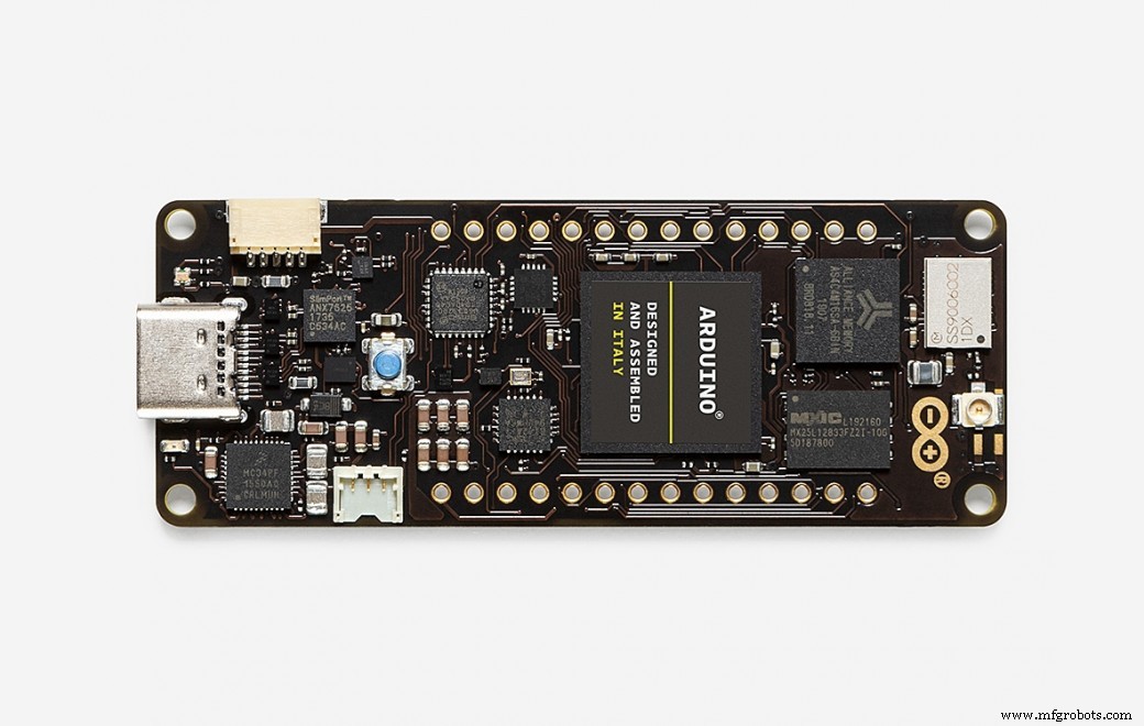
The Arduino Portenta H7 delivers a powerful dual‑core architecture: a Cortex‑M7 running at 480 MHz and a Cortex‑M4 at 240 MHz. The two cores can run independent firmware and communicate via shared memory or semaphores.
Debugging both cores simultaneously requires a dedicated SWD interface and a debugger that supports multi‑target sessions. In this guide we show how to use a Segger J‑Link to connect to each core, set up the development environment, and run a simple blink example that demonstrates independent control of each core’s LED.
Hardware Setup
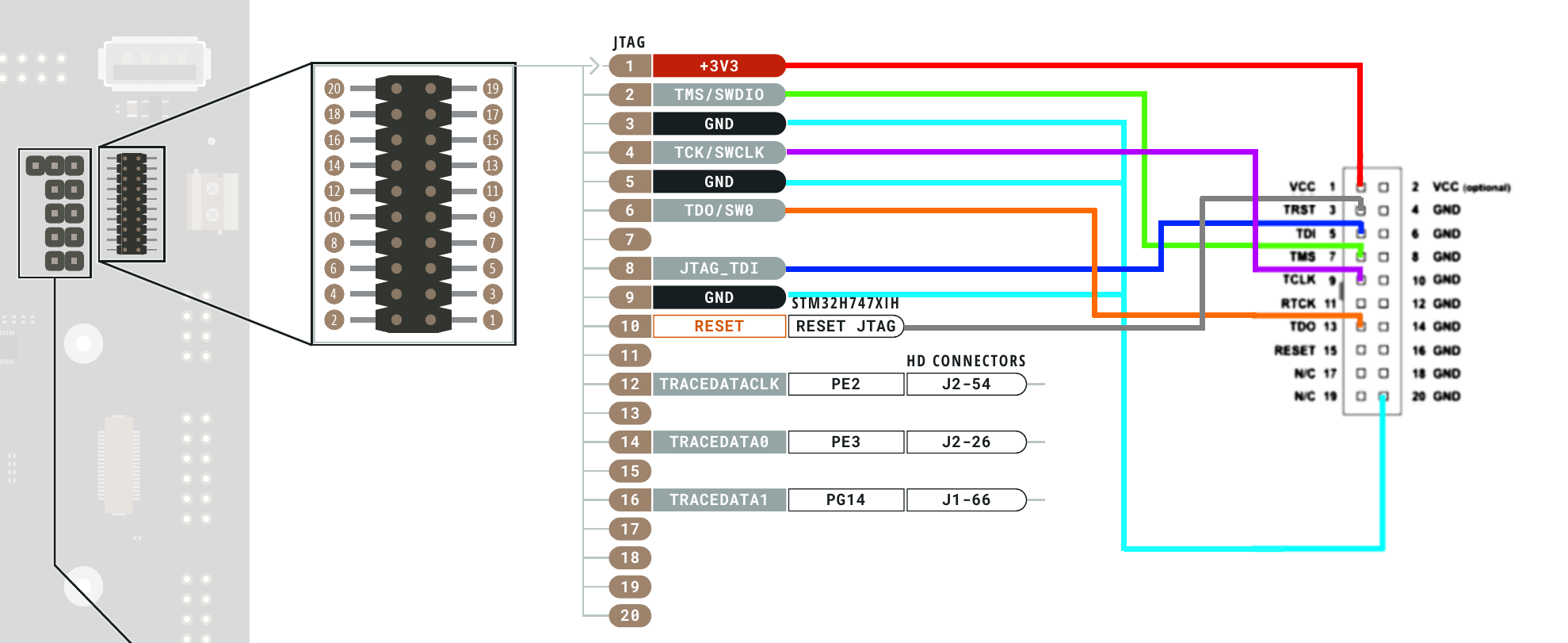
1. Mount the Portenta H7 on its breakout board. The board exposes a 20‑pin MIPS‑style header that connects to the SWD pins of both cores.
2. Attach a 20‑pin MIPS converter to the breakout header to separate the debugging signals.
3. Wire the converter to the Segger J‑Link according to the pin‑out diagram below. If you prefer a custom solution, use 0.05‑inch pitch connectors and follow the example wiring shown in the second image.


Software Setup
1. Install the Arduino IDE (download from Arduino website).
2. Install Microsoft Visual Studio (2017, 2019 or 2022) and the Visual Micro extension (full instructions are available on the Visual Micro website).
3. Add the Arduino Mbed OS Portenta Boards package via the Visual Micro Explorer or the Boards Manager in the Arduino IDE.
4. Replace the USB driver on Interface 0 of the Segger J‑Link with the WinUSB driver using Zadig. A short walkthrough video is linked below.
Let’s Code
Prepare two separate projects, one for each core. The following Blink examples light a different LED on each core and can be debugged independently.
Important: In the M7 project call bootM4() at the beginning of setup() to ensure both cores are active.
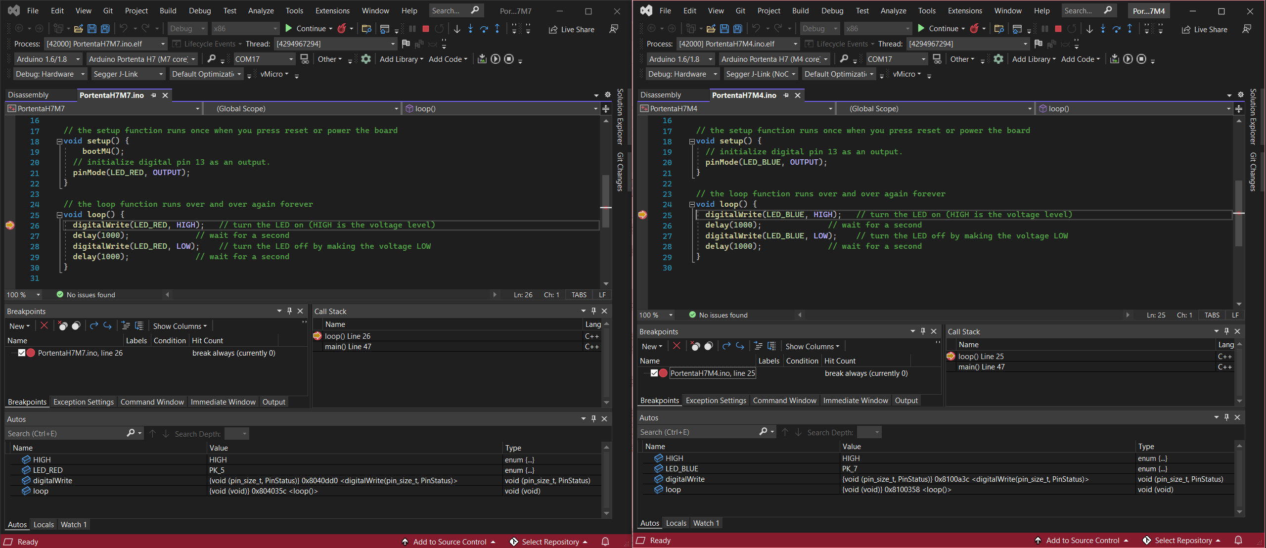
Debug Setup: M7 Core
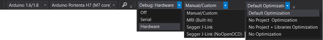
Open the M7 sketch in Visual Studio, go to Debug > Hardware and select Segger J‑Link Debugger (not the NoOpenOCD version). Build and upload the sketch to the M7 core.
Debug Setup: M4 Core
Open the M4 sketch, choose Debug > Hardware, and select Segger J‑Link Debugger (NoOpenOCD). Build and upload to the M4 core.
Start the Debugger
First launch a debugging session for the M7 sketch using Debug > Attach to Process. Repeat the same step for the M4 sketch. You can now set breakpoints in either project, pause, step, or continue independently—each core responds to its own commands.
Walkthrough Video
Watch a step‑by‑step demonstration on YouTube:
Useful Links
Code
- H7 M4 Blink Code
- H7 M5 Blink Code
H7 M4 Blink CodeArduino
// Blink on the Portenta M4 Core
void setup() {
  pinMode(LED_BLUE, OUTPUT);
}

void loop() {
  digitalWrite(LED_BLUE, HIGH);
  delay(1000);
  digitalWrite(LED_BLUE, LOW);
  delay(1000);
}
H7 M5 Blink CodeArduino
// Blink on the Portenta M7 Core
void setup() {
  bootM4();              // Activate the M4 core
  pinMode(LED_RED, OUTPUT);
}

void loop() {
  digitalWrite(LED_RED, HIGH);
  delay(1000);
  digitalWrite(LED_RED, LOW);
  delay(1000);
}
Schematics
How to connect the SWD pins on the Breakout Board to the Segger J‑Link:
Manufacturing process
- Arduino Launches Portenta H7: Industrial‑Grade IoT Board Debuts at CES
- Build a Bluetooth‑controlled Arduino Spybot
- FlickMote: Gesture‑Controlled IR Remote for Smart Home
- DIY Arduino TV B-Gone: Universal Remote for All TVs
- Build a Custom LED Master Clock with Alarm – Viewable from 12 Meters
- Find Me: Smart Item Locator with Arduino and Bluetooth
- Optimized Power Solutions for Arduino Projects
- Arduino Tic Tac Toe with MAX7219 LED Matrix and Cardboard Enclosure
- Smart Water Leakage Detection and Valve Control System
- Securely Link Arduino MKR GSM 1400 to Google Cloud IoT Core: Step‑by‑Step Guide