


Understanding Pin Joints in Mechanical Engineering
In mechanical engineering, there are multiple methods for fastening objects together. A pin joint is a solid cylinder-shaped device, similar to a bolt, which is used to connect objects at the joint area. This type of joint connection allows each object to rotate at the point of joint connection.
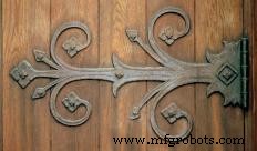
Most mechanical devices that require bending or opening typically use a pin joint. These joints can be welded solid or allow movement between the two connected objects. A door hinge is a simple example of a free-moving pin joint. The hinge has a pin that allows the door to connect and open freely in the door jam. In this design, the pin is the only device holding the door hinge to the door jam.
A steel-framed truss bridge is an example of a solid-welded pin joint. These bridges have steel beams of multiple angles that are connected together with solid pins. These pins allow the connection of severe angles within the bridge support systems. The solid pins are typically bolted together at the joint area and welded tight. This adds strength and prevents the joints from collapsing under stress.
A cotter key is another example of a pin joint. This is a small cylinder-shaped device that is typically inserted into a hole to prevent movement. The cotter key is used with a special nut and bolt that contains a hole for the key. This is the safety device that secures the the wheels of a car onto an axle. Because the cotter key is a pin that is inserted between the bolt and nut, it prevents a nut from loosening over time.
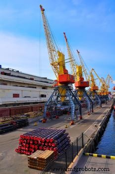
Large construction equipment uses pin joints. Heavy loaders, cranes, and backhoes all use pins to connect sections of the machine at the joint area. With a backhoe, the joint is used between the arm and the bucket connection. This pin design allows the bucket to move independently of the arm. The movable joint area allows the bucket the bend freely.
The pin joint design has been used for centuries to create connections between objects. With construction of homes, decks, and bridges, beams are connected to the columns, creating a strong grid that will keep a building stable. This design is used to create multiple levels of a home. The joint area of each beam is securely fastened with pins to create a stronger foundation.
Industrial equipment
- Bent Hitch Pins Explained: How They Work, When to Use Them, and How to Choose the Right One
- Loose Joint Hinges: Design, Function, and Advantages
- Mechanical Joints Explained: Types, Uses, and Common Failure Points
- Cotter Pins Explained: How They Secure Bolts and Keep Machinery Stable
- Understanding Tee Joints: Types, Applications, and Construction
- Understanding Housing Joints: A Strong, Simple Woodworking Connection
- Understanding Screw Joints: Definition, Uses, and Advantages
- Understanding Joint Tape: How It Smooths Drywall Joints for a Seamless Finish
- What Is a Gudgeon Pin? The Essential Wrist Pin in Engine Design
- Knuckle Joint Explained: Design, Applications, and Key Features