


Using RGB LED Blinking for Debugging When No Serial Port Is Available
In high‑density or cost‑constrained embedded designs, a traditional UART or USB debug port is often omitted. When that happens, a simple RGB LED can become an effective diagnostic channel.
During recent freelance projects, I encountered two scenarios where clients had not provisioned any textual debugging interface. In one case the hardware team forgot to add a serial port before committing to mass production; in the other, the device was so compact that a dedicated debug connector was physically impossible. In both situations, the boards included an RGB LED that could be leveraged for state indication.
By assigning distinct colors to code contexts and encoding messages through blink counts and patterns, the LED can convey a wide range of information—essentially functioning as a “human‑readable” log.
My implementation defined four rhythmic patterns, each exposed through a dedicated API function:
led_debug_blink(color, count)– short blinks (1 s on, 0.5 s off) for routine messages.led_debug_blink_wide(color, count)– longer blinks (2 s on, 0.5 s off) for significant events.led_debug_blink_error(color, count)– error blinks that begin with a red flash followed by the context color.led_debug_blink_wide_error(color, count)– extended error blinks with the same red‑precedence.
Each call queues the pattern so that the LED displays them sequentially, mirroring how a console log would buffer short messages.
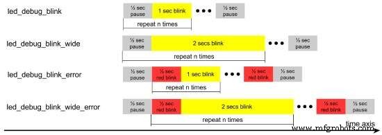
Blink timing diagram for the four standard and error debug functions (click for larger image). Source: Felipe Lavratti
The diagram shows yellow regions that represent the chosen context color. Aside from black (LED off) and red (error), any of the remaining RGB combinations—green, blue, yellow, cyan, magenta, or white—can be used to identify a module or function. Pulse‑width modulation can extend the color palette, but inexpensive LEDs often struggle with precise mixing, so simple primary colors or bright secondary hues (e.g., orange) are most reliable.
Careful selection of blink durations and intervals ensured that the patterns are legible to engineers on the bench and to field technicians during field‑service. The key is to avoid flooding the LED with messages; a disciplined coding style keeps the display informative without becoming noisy.
While an LED is never a replacement for a full serial console, in the systems I worked on it accelerated both development and on‑site diagnostics. After a brief training session, the team quickly understood the color‑code scheme and could pinpoint faulty code paths just by watching the LED.
This experience demonstrates how a modest design tweak—tuning the LED’s capabilities to human perception—can transform a crude interface into a powerful debugging aid.
Felipe Lavratti has developed Internet‑connected home‑automation devices, built embedded Linux applications and drivers for handheld point‑of‑sale terminals, and implemented embedded mathematical algorithms for process control and industrial data loggers. Recognizing the value of quality early in his career, Felipe applies modern best practices to ensure robust products—from coding and testing to acceptance and deployment. He currently works as a freelance consultant and developer and can be contacted at …
Embedded
- Maxim’s MAX25610A/B LED Drivers: Compact, High‑Efficiency, and EMI‑Optimized for Automotive & Industrial Lighting
- Unexpected Intruders: How Mice, Bats, and Bearing Defects Threaten Industrial Reliability
- Arduino RGB LED Color Mixer – Beginner‑Friendly DIY Project
- Outdoor DMX-Enabled RGB LED Flood Lights – Affordable & High-Performance
- RGB LED Backlight with MSGEQ7 Audio Visualizer for TV and Desk
- Create Your Own LED Color Sequencer with Arduino – Easy DIY Tutorial
- Motion‑Activated RGB LED Color Changer – Arduino Project
- Build an 8x8x8 RGB LED Cube with Arduino – DIY Guide
- Smart Staircase RGB LED Lighting System – Motion-Activated & Easy to Install
- The Origin of the Metal-Working Lathe: A Historical Overview