


Understanding Battery Management Systems (BMS): Core Concepts and Key Components
Explore the essential role of battery management systems and the foundational components that enable safe, efficient power design.
Today’s high‑performance Li‑ion batteries deliver energy densities of up to 265 Wh/kg, yet their power can be hazardous if they are overstressed. Battery Management Systems (BMSs) are the safeguard that keeps these cells operating within safe limits, preventing thermal runaway and prolonging life.
This article walks through the fundamental principles of BMS architecture and examines the core parts that make up a typical system.
Basic BMS Configurations
Figure 1 illustrates the common building blocks of a BMS designed to protect against major faults.
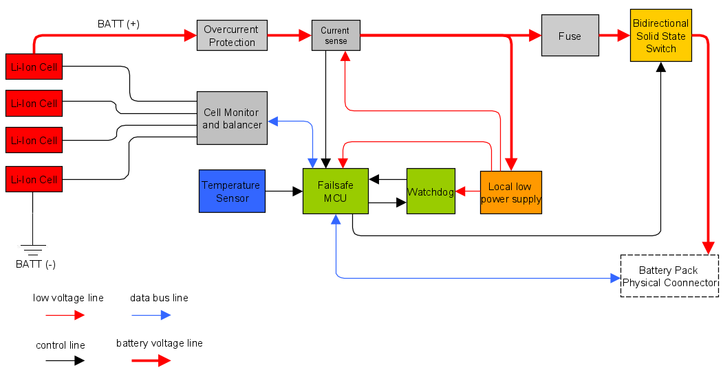
Figure 1. A typical BMS block diagram
The example manages four Li‑ion cells in series. A cell monitor reads each cell’s voltage and balances the pack, while an MCU controls telemetry, switch logic, and balancing strategy.
For simpler applications, the market offers streamlined solutions that omit balancing or an MCU, as shown in Figure 2.
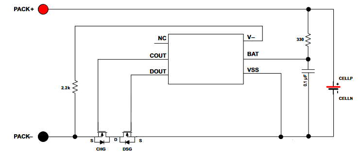
Figure 2. A simple battery manager. Image courtesy of Texas Instruments
These minimal designs limit flexibility, binding the designer to the vendor’s chosen switches and features.
When a pack grows larger or requires accurate state‑of‑charge calculations, an MCU‑based solution becomes necessary. Figure 3 presents a basic, MCU‑independent balancer, while Figure 4 shows a fully integrated commercial BMS from Renesas.
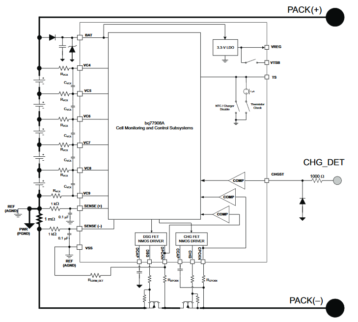
Figure 3. An MCU‑independent cell balancer. Image courtesy of Texas Instruments
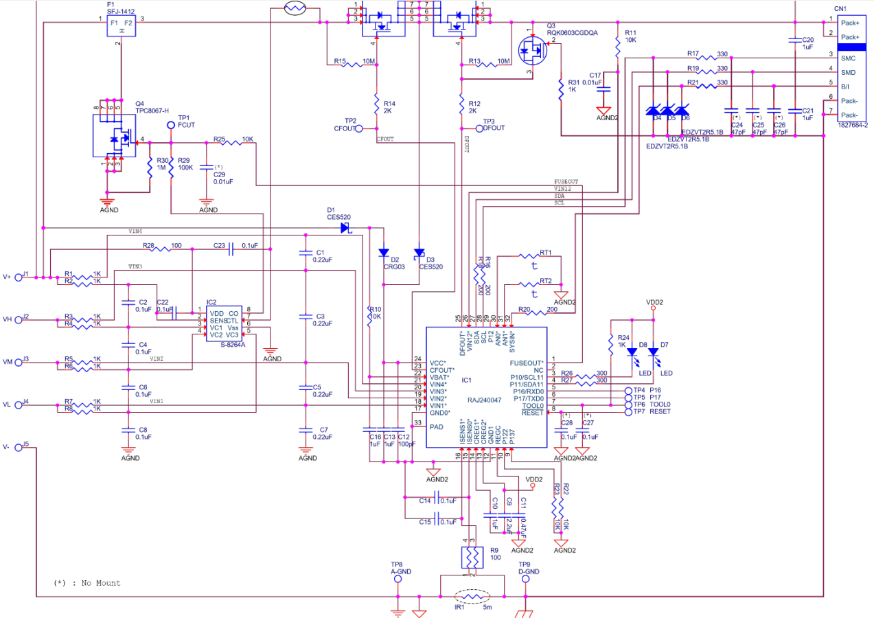
Figure 4. A commercial BMS. Image courtesy of Renesas
The Building Blocks: Battery Management System Components
Reviewing Figure 1 gives a high‑level view. Below we detail the key elements seen in Figure 4, explaining their roles in a BMS architecture.
Fuse
Rapid protection from a short circuit is achieved with a self‑control protector (SCP) fuse, which is triggered by the over‑voltage control IC when it pulls pin 2 to ground.
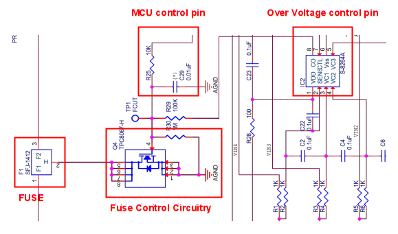
Figure 5. SCP fuse and control of a commercial BMS
Because the MCU must detect a blown fuse, the power supply to the MCU is placed before the fuse.
Current Sensing / Coulomb Counting
Low‑side current sensing provides a direct interface to the MCU. By integrating current over time, the system implements a Coulomb counter that estimates the state of charge (SOC).
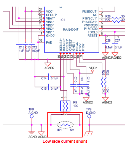
Figure 6. Typical low‑side current sense of a commercial BMS
The SOC calculation follows the formula displayed in Figure 7:

where
• SOC(t₀) is the initial SOC (Ah)
• Crated is the rated capacity (Ah)
• Ib is the battery current
• Iloss accounts for cell reaction losses
• τ is the averaging period of the current samples
Thermistors
Thermistors serve dual purposes: temperature monitoring and safety shutdown. One thermistor can directly trigger the SCP fuse when temperatures become critical, as shown in Figure 8.
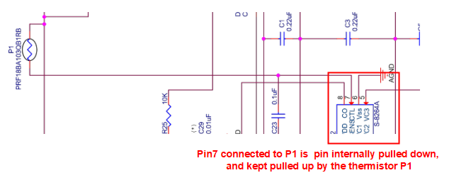
Figure 7. A thermistor can control the SCP, in case of severe thermal problems
Additional thermistors provide telemetry for firmware‑based temperature management, illustrated in Figure 9.
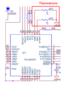
Figure 8. Thermistors used by the firmware
Main Switch
MOSFETs in the BMS act as high‑ or low‑side switches. Proper gate‑drive voltage (Vgs) ensures low on‑state resistance (RMOS) and minimal conduction losses. Figure 10 depicts a high‑side NMOS controlled via a charge pump.
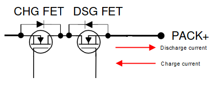
Figure 9. Battery pack main switch (NMOS, high‑side)
Balancer
Cell tolerances lead to voltage mismatches over cycles. A weaker cell can over‑charge if the pack continues to charge, or a stronger cell can discharge too quickly, risking undervoltage. Balancing mitigates both scenarios.
Figure 11 shows how an unbalanced pack limits full charge, while Figure 12 demonstrates a passive charge‑shunting strategy that equalizes cell voltages.
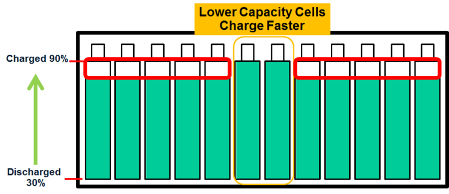
Figure 10. Lower capacity cells impeding pack full charging. Image courtesy of Analog Devices
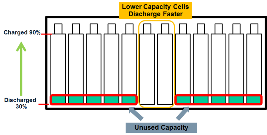
Figure 11. Lower capacity cells impeding usage of full pack energy. Image courtesy of Analog Devices
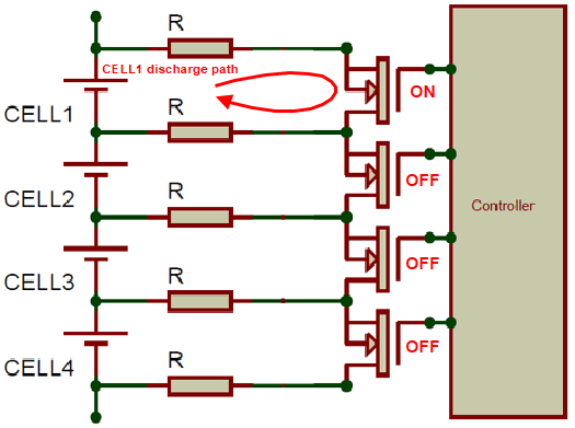
Figure 12. Example of passive balancing strategy
This article has introduced the foundational concepts of Battery Management Systems and highlighted the critical components that enable safe, efficient operation. We hope it deepens your understanding of BMS design and its role in power electronics.
Have more BMS topics you’d like to explore? Share your thoughts in the comments below.
Embedded
- 7 Key Advantages of Computerized Maintenance Management Systems (CMMS)
- 3D Systems Figure 4 Production – High‑Volume Resin 3D Printing Solution
- 3D Systems Figure 4 Modular: Scalable, Semi‑Automated 3D Production for Low to Mid‑Volume Manufacturing
- 3D Systems Figure 4 Standalone: High‑Accuracy, Industrial‑Grade 3D Printing for Low‑Volume Production
- EV Safety Relies on Advanced Battery Management
- Optimizing Motor Drivers for Battery‑Powered IoT Devices
- The Core of EVs: A Comprehensive Guide to Battery Systems
- Four Essential Benefits of Inventory Management Systems
- Mastering Profile Cutting Systems: Advanced Techniques for Modern Metalworking
- Mastering Manufacturing Automation: Strategies, Benefits, and Industry 4.0 Insights