


Build a Reliable Fire Alarm Circuit with a Thermistor – Step‑by‑Step Solderless Breadboard Project
In everyday life, we rely on a range of electronic devices—door‑bell systems, TV remotes, automated lighting, fire alarms, and more—each built upon foundational electronics projects. This article explores a straightforward fire alarm circuit that leverages a thermistor for temperature detection.
Fire Alarm Circuit
A fire alarm circuit is the first line of defense against fire hazards in homes, offices, and industrial settings. By detecting a sudden rise in temperature, the circuit triggers an alert that can prevent property damage and save lives.
Electronics Projects
Common household electronics—such as automatic outdoor lighting, fan regulators, night‑sensing lights, kitchen timers, and disco lighting—are often built on breadboard prototypes. These solder‑less setups allow rapid testing and component reuse before committing to a permanent PCB design.
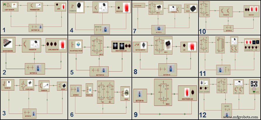
5‑Simple Steps to Build a Fire Alarm Project
This mini‑project uses a thermistor‑based temperature control system that can be assembled on a solder‑less breadboard. The following five steps guide you from concept to a functional alarm.
Step 1: Block Diagram Design
The starting point is a clear block diagram that outlines the core elements: a thermistor, a transistor, an indicator (LED), and a power source. The diagram determines the signal path and component placement.
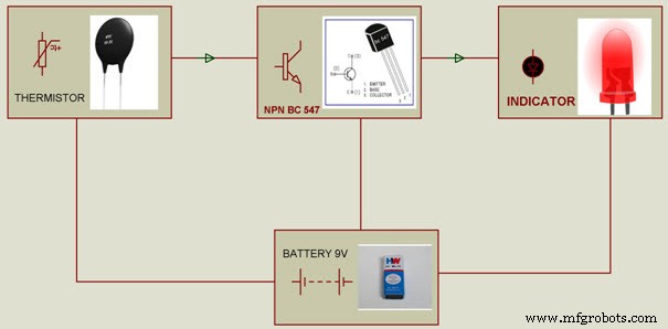
A clean schematic reduces wiring errors and makes troubleshooting straightforward.
Step 2: Gather Components

Essential parts include a negative‑temperature coefficient (NTC) thermistor, an NPN transistor (e.g., 2N2222), an LED, a suitable resistor, and a 3‑V or 5‑V battery. Components can be sourced from reputable suppliers such as EdgeFXKits, which offers project kits ranging from individual parts to fully assembled DIY bundles.
Step 3: Assemble on Breadboard
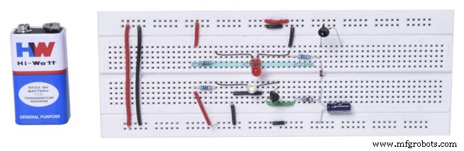
Using jumper wires, connect the thermistor to the base of the transistor, route the collector to the LED, and tie the emitter to the battery negative. A pull‑up resistor on the base ensures proper biasing. Once the circuit behaves as expected on the breadboard, you can proceed to a PCB.
Step 4: Transfer to PCB and Solder

Solder the same layout onto a printed circuit board to secure the connections and reduce the risk of accidental disconnection. Use a fine‑tip soldering iron and ensure clean joints for reliable operation.
Step 5: How the Alarm Works
The NTC thermistor’s resistance falls as temperature rises. This change pulls the transistor’s base toward ground, turning the transistor on and allowing current to flow through the LED. The LED lights up when the temperature surpasses the preset threshold, signaling a potential fire.
For applications demanding higher precision, replace the thermistor with a digital temperature sensor such as the DS18B20, and use an operational amplifier or microcontroller to generate a proportional output. The same basic concept can be expanded into an automated firefighting robot that deploys water when the sensor detects a critical temperature.
The thermistor-based design is cost‑effective, simple to build, and offers dependable performance for a first‑level fire detection system.
Ready to tackle a hands‑on electronics challenge? Share your thoughts, suggestions, or design ideas in the comments below.
Sensor
- Building and Troubleshooting a Basic 6‑V Battery‑Lamp Circuit
- Designing a Four‑Digit 7‑Segment Display with a Single Binary Encoder
- Understanding Simple Series Circuits: Key Principles and Practical Examples
- Building Resistor Circuits: From Alligator Clips to PCBs
- Fundamentals of AC Circuit Calculations: From Resistance to Kirchhoff’s Laws
- Parallel Tank Circuit Resonance: Theory, Calculations, and SPICE Verification
- Inductive Proximity Sensor: Circuit Design, Functionality, and Practical Applications
- Electronic Eye Security Circuit: LDR & 4049 IC for Light‑Sensitive Control
- Build a Reliable Overvoltage Protection Circuit with a Zener Diode
- Build Your Own Theremin: A Beginner's Guide to DIY Electronic Sound