Industrial manufacturing
Industrial Technology

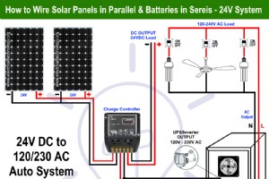
Wiring Batteries in Series and PV Panels in Parallel – 24V Installation While most of the domestic PV panels installation are in 12VDC systems, there are cases where we need 24V or additionally 36V, 48V and so on depending on the system requirements. Moreover, we need to connect the s

Star to Delta and Delta to Star Transformation – Y-Δ Conversion In an electrical network, the impedance can be connected in various configurations. The most common of these configurations are either star or delta connected network. To solve complex electrical networks or simplify it,
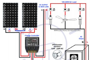
Wiring Batteries in Parallel and PV Panels in Series – 12-24-48V Installation Generally, the 12V system for both solar panels and batteries are very common in residential PV panel installation systems. In more complex and heavy load systems, 24, 36, 48, 72VDC (and so on) are used base
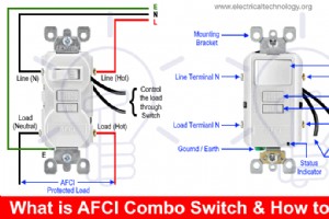
AFCI Combo Switch Wiring Circuit Diagrams and Installation Arc fault circuit interrupter “AFCI” is a protection device used to protect the circuit from electric arcing which cases electric fire. It detects the arc and disconnect the circuit from main power supply. In our previou
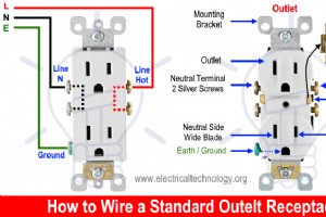
How to Wire and Install an Electrical Outlet Receptacle? What is an Electrical Outlet, Receptacle or Socket Outlet? Electrical Outlet (NEC) is also known as Receptacle and more commonly a Socket Outlet (IEC). According to NEC, an outlet is the point(s) in an electrical wiring system where
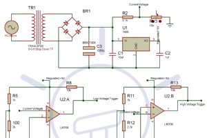
Electronic Circuit Breaker – Circuit Diagram, Working and Applications AC device that we use in our homes generally have a limit to handle the current and voltage. These threshold voltage and current are called the device rating, and are the measurements given by the manufacturers in
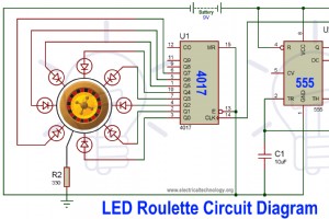
Flashing LED Roulette Circuit Diagram using 555 Timer & 4017 ICs There is a casino game and a French word accompanying it called “Roulette”. This circuit resembles the functioning of a Roulette wheel game, hence the name given to it. This circuit consists of a timer IC and a special IC
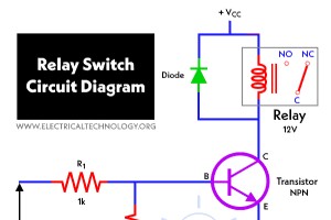
Electronic Relay Switch Circuit Diagram and Its Working There are a variety of electrical and electronic devices which are classified as Output devices such devices are used to control or operate some external physical process of a machine or device. These output devices are commonly called
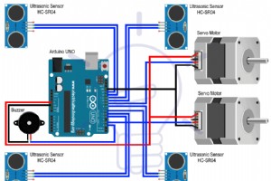
High Speed Auto Railway Gate Controller Circuit Using Arduino and Ultrasonic Sensors In this tutorial, we will learn how to design a simple and efficient automatic high-speed railway gate controller system. This is a relatively simple approach to this project but you can take this as a basi
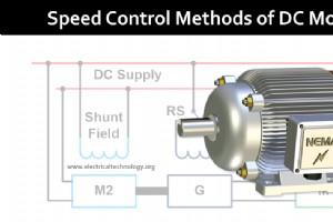
Speed Control Methods of DC Motor – Voltage, Rheostatic & Flux Control of Series & Shunt DC Motors A DC motor is used to convert the direct current (DC) electrical power into mechanical power based on the forces produced by magnetic filed(s). The output of the motor is mechani
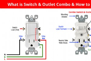
Switch and Outlet Combo Device Wiring Diagrams and Installation What is Combo Switch/Outlet Device and How to Wire It? A combo device is the combination of switch and outlet in the same enclosure box. The built-in switch can be wired to control the receptacle in the enclosure box. The swit
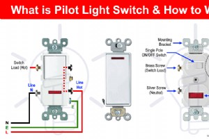
How to Wire 2 & 3 Way Neon Pilot Light Switches What is a Pilot Light Switch and How to Wire It? A pilot light switch contains on a switch and a builtin neon bulb which glows when switch is ON and power flows through it to the lighting point or any other connected load or appliances. P

AC Single Phase & Three Phase And DC Wire & Cable Color Codes Electrical engineers, contractors, traders, manufacturers and especially electricians around the world use different electrical wiring color codes for cable and wire installation and electricity distribution in industrial
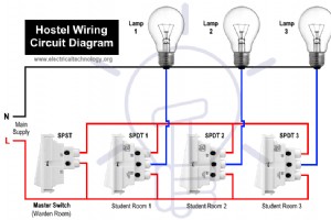
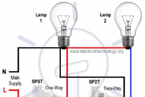
Hostel Wiring Circuit Diagram and Its Operation Hostel wiring circuit is especially designed and used for study hours by headmasters and wardens to convey the students to do their study instead of early sleeping. In hostel wiring circuit, there is a SPST (single pole single throw or one way
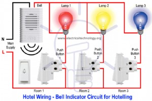
Bell Indicator Circuit Wiring Diagram for Hotelling Bell indicator circuit is used where a bell and buzzers are needed to control from different locations. Bell Indicator circuit is also known as hotelling circuit where an electric bell is controlled from more than one locations. In hotel w
Light Control Circuit by Switches for Patient in Hospital Rooms We call it “Hospital wiring circuit” by using only switches and lamps to control the lighting density of bulbs in a room especially for admitted patients in the hospital. Although, we can control the lighting densit
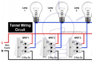
Tunnel Wiring Circuit Diagram – Working and Operation Tunnel wiring circuit is used in open ended corridors and short tunnels like structures. In tunnel wring circuit diagram, we have used SPDT (two-way) switches to control the lighting points in tunnels and corridors. The tunnel circ
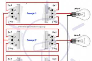
Hallway and Corridor Wiring Circuit Diagram using Two Way Switches Basically, this circuit is same like staircase wiring circuit using two-way (SPDT) switches used to control the lighting circuit in a hallway and corridors. In corridor wiring circuit, a lighting point is controlled from two
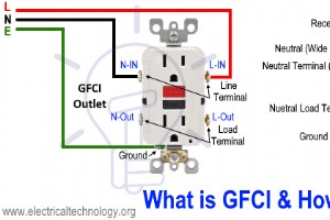
How to Wire and Install a GFCI Outlet? What is a GFCI? GFCI also known as “Ground Fault Circuit Interrupter” is a protective device which automatically detects the ground faults and leakage current and provides personal protection against electrocution. GFCI as an outlet / rece
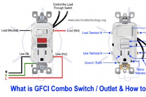
GFCI Combo Switch and Outlet Wiring Circuit Diagrams and Installation As discussed before, GFCI also known as ground fault circuit interrupter is a protection device against electric shock which detects the ground faults and leakage currents especially in outdoor and watery areas such as ba
Industrial Technology