


Affordable Arduino Breath Controller with USB-MIDI Integration
Components and supplies
 |
| × | 1 | |||
 |
| × | 1 | |||
| × | 1 | ||||
| × | 1 | ||||
 |
| × | 2 | |||
 |
| × | 1 | |||
| × | 1 | ||||
| × | 1 | ||||
| × | 1 |
Necessary tools and machines
 |
|
Apps and online services
 |
|
About this project
IntroductionIn this project we will build a simple USB MIDI plug-and-play breath controller. It is designed using easy to find cheap components so that the total cost remains affordable and well below commercial equivalents. This is the basic version that only uses the air pressure sensor but the plan is to upgrade it to include a bite and nod/tilt sensor in the future.
The project assumes some very basic electronics and Arduino knowledge but even a beginner can build it as there is no soldering involved. Of course more advanced users can solder everything on a perma-protoboard. I am not covering installation of the IDE/libraries and instructions to upload code as there are excellent tutorials on the internet.
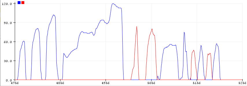
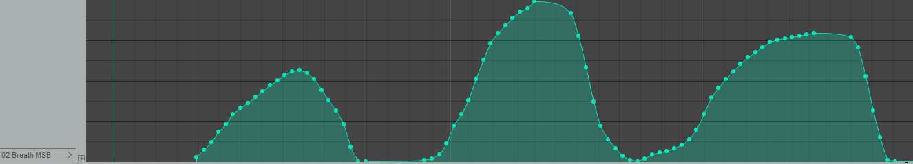
Oversampling is used to smooth out the sensor's input with very good results. You can also adjust the range to your liking and even dial in custom curves to adjust the controller's behavior.
Since the sensor can measure negative pressure too, there is a second stream of controller messages that is output when you draw in air instead of blowing. Both types of messages can be set by the user. For example you can set blow to pitch bend up and draw in to pitch bend down. By default both are set to controller no. 2.
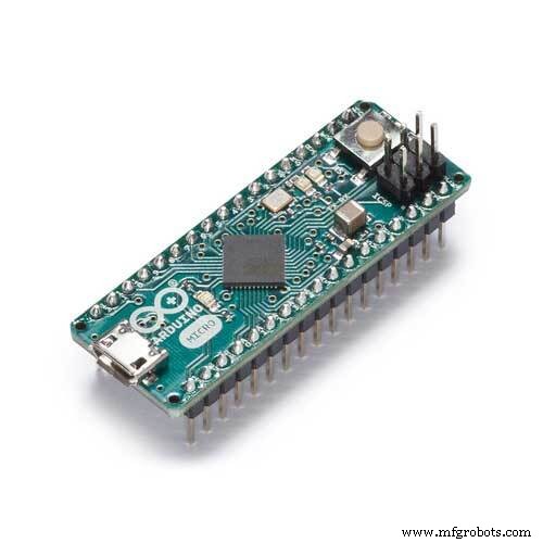
Steps to build1. Insert the Arduino to the breadboard as shown in the photo/schematic.
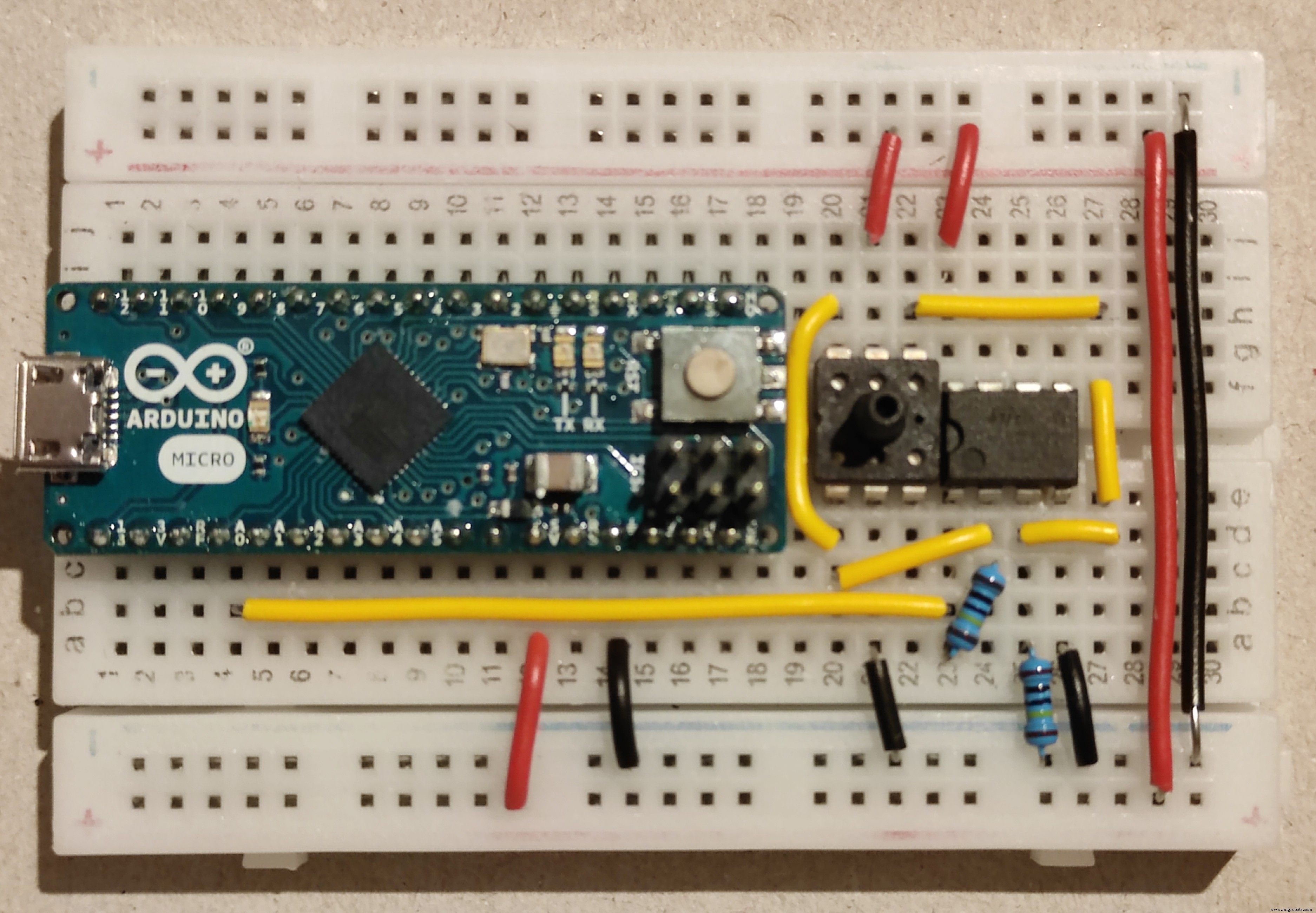
2. Insert the sensor and op amp to their respective positions, notice the orientation based on the small indents on their sides.
3. Insert the resistors after cutting their legs to appropriate lengths.
4. Cut/strip the solid core cables and place them in their respective positions. I have used red for 5V, black for ground and yellow for signal in order to make this easier to understand but you can of course use whatever you have available.
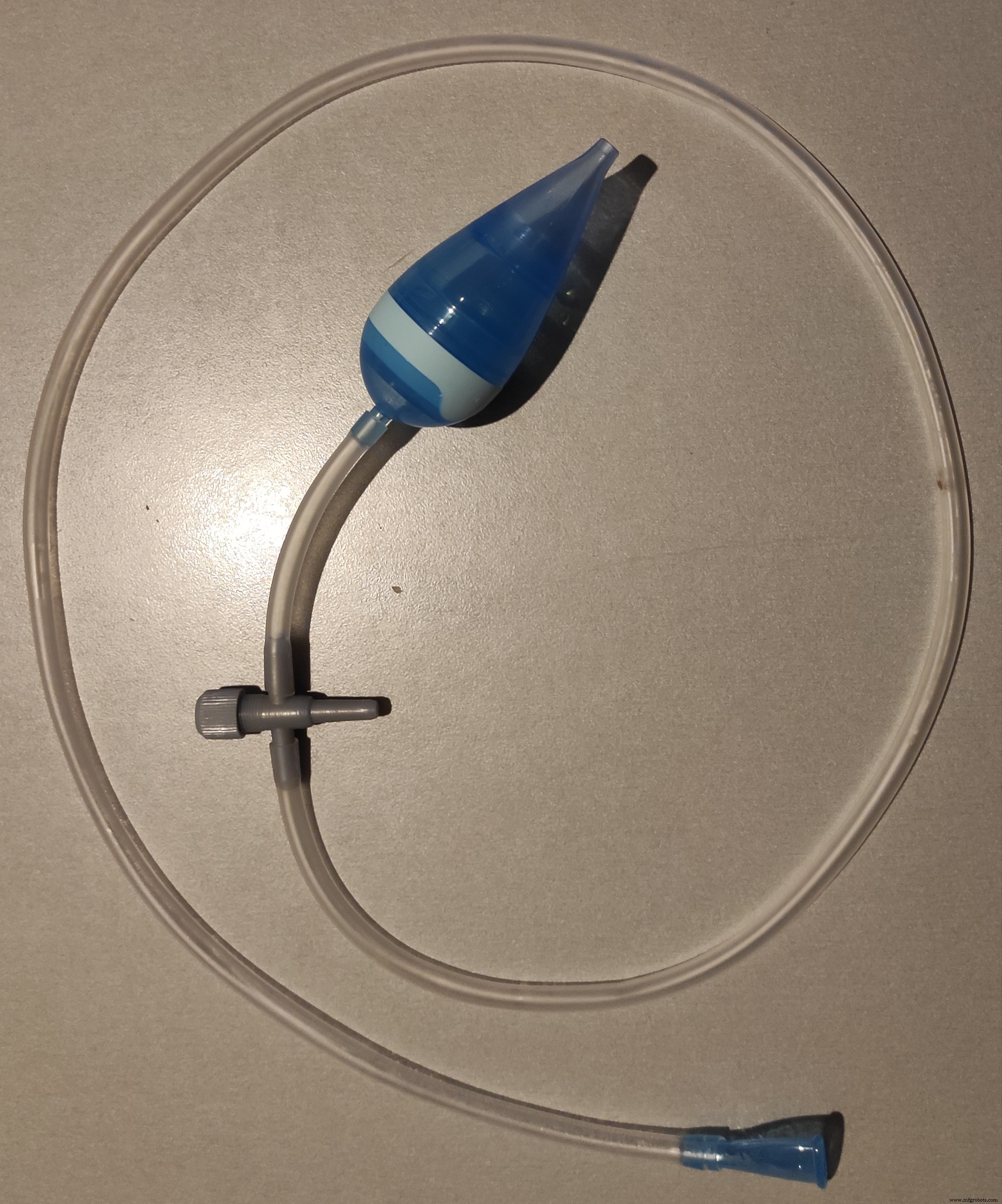
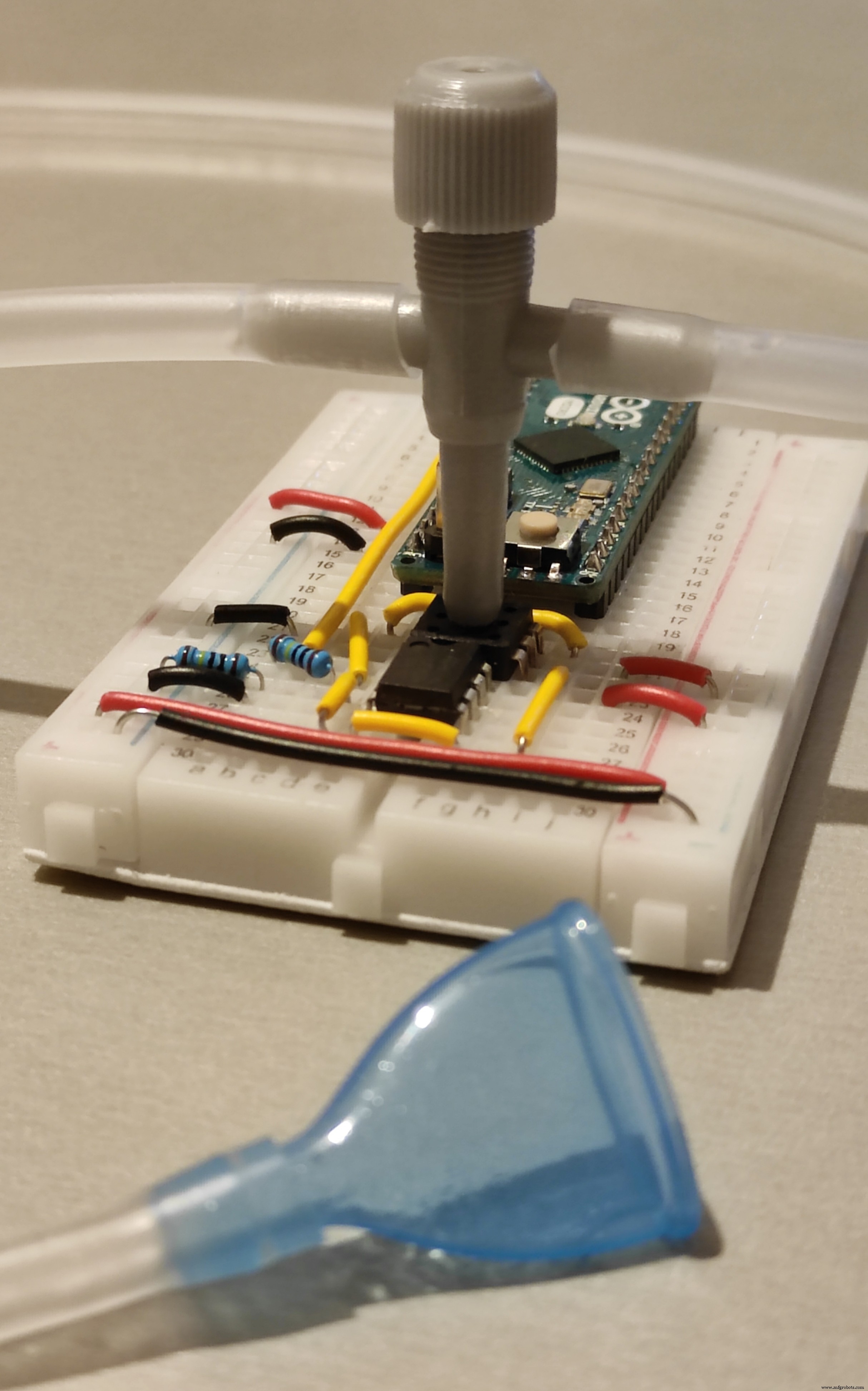
5. Connect the mouthpiece, tubing, 3-way connector and aspirator as shown in the photo. You will need to cut a piece of the tubing for the "exhaust".
6. Press the 3-way connector so that it fits onto the sensor. It should stay put.
7. Install the Arduino IDE and install the two libraries needed (Oversampling and USB-MIDI) from Tools->Manage Libraries. Connect the Arduino with a USB cable to your computer. Upload the attached code.
8. You should be set, the Arduino should now appear as a MIDI device in your DAW/Music Software. Enable it and route it along with your keyboard to a plug-in that supports breath controller.
One physical drawback of this design is the saliva that will inevitably flow in the tube and can cause noticeable air flow fluctuations. The 3-way connector is used to address this issue by routing the saliva to the "exhaust" tube. To minimize trapped saliva in the tube, make sure that there is a continuous slope from the mouthpiece to the 3-way connector by adjusting the tubing length. If the tube hangs beneath the 3-way connector level, saliva will be trapped at its lower point causing fluctuations. The baby-side part of the aspirator including its filter is attached to the exhaust to minimize dripping as well as noise and increase the flow of air to the sensor.
In the code there are values that you can adjust to your liking, including custom curves. Comments describe how to do this. If you find it hard to reach the 127 point decrease the maximum range, or if it is too easy, increase it. Whenever you change values, you will need to reupload the code.
First few readings after Arduino boot are averaged to calibrate the rest position. Do not blow into the tube while connecting/resetting the device.
You can change the name of the MIDI device by editing the boards.txt file (info on how to do this for each platform is available on the internet).
Code
- Breath controller code
Breath controller codeArduino
Upload this code to your breath controller via Arduino IDE/*
Breath Controller
*/
//Libraries used - install them from Tools->Manage Libraries
#include <Oversampling.h>
#include <USB-MIDI.h>
//Debug mode (uncomment to enable)
//#define DEBUG 1
//Creation of the USB MIDI interface
USBMIDI_CREATE_DEFAULT_INSTANCE();
//Oversampling init
Oversampling adc(10, 13, 6);
// ***************** User Setup *****************
// Values ending in 1 correspond to blowing while those ending in 2 to drawing in air
// Pin setup
const int sensorPin1 = A0; // select the Arduino input pin for the Sensor/Op Amp output
// Range Calibration. Adjust this manually so that you can reach maximum but not too easily.
int sensorRange1 = 800;
int sensorRange2 = 800;
// Output controller number. Select from below table
// 0-127: regular control change messages
// 128: monophonic aftertouch
// 129: Pitch Bend Up
// 130: Pitch Bend Down
int controllerNumber1 = 2; // Controller sent when blowing
int controllerNumber2 = 2; // Controller sent when drawing in air
// Output controller channels
int controllerChannel1 = 1;
int controllerChannel2 = 1;
// Safety thresholds for lowest and highest values to avoid fluctuations when at rest or max.
// If multiple messages are sent when at rest increase the lowThreshold.
// If multiple messages are sent when at max increase the highThreshold.
const int lowThreshold1 = 5;
const int lowThreshold2 = 5;
const int highThreshold1 = 0;
const int highThreshold2 = 0;
// Curve definition. Tables can have any legth equal or larger than 2. Values can be 0-127 . Tables should have the same number of elements and "in" tables should be in ascending order.
// Conversions are done at a readings level so loss of definition is minimized.
int in1[] = {0, 127};
int out1[] = {0, 127};
int in2[] = {0, 127};
int out2[] = {0, 127};
// Example curves (modify sensor number accordingly)
//Soft
//int in1[] = {0, 6,24,78,127};
//int out1[] = {0,32,64,96,127};
// Reduced range
//int in1[] = {50, 100};
//int out1[] = {50, 100};
// Refresh Cycle (milliseconds). Lower values mean more messages are sent during operation.
int refreshCycle = 0;
// ***************** Implementation *****************
// Do not modify from this point and onward if you do not intent to alter the operation of the sensor.
// Internal Value of Sensors
int sensorValue1 = 0;
int sensorValue2 = 0;
// Minimum sensor values
int sensorMin1;
int sensorMin2;
// Output controller values
int controllerValue1 = 0;
int controllerValue2 = 0;
// Previous cycle values used to avoid repetition of identical messages
int previousControllerValue1 = 0;
int previousControllerValue2 = 0;
// Range conversion variable init
int outputRange1;
int outputRange2;
int sensorLow1;
int sensorLow2;
int sensorHigh1;
int sensorHigh2;
void setup() {
MIDI.begin(1);
#ifdef DEBUG
Serial.begin (115200); //Only for debug mode
#endif
// Calibrate sensor's rest point by averaging 10 first values. Do not use the sensor while booting the device.
sensorMin1 = adc.read(sensorPin1);
sensorMin2 = 0;
// Determine output ranges for the controllers chosen
outputRange1 = outputRange(controllerNumber1);
outputRange2 = outputRange(controllerNumber2);
}
void loop() {
// read the value from the sensor:
sensorValue1 = adc.read(sensorPin1); // Blowing air
sensorValue2 = sensorMin1 - sensorValue1; // Drawing in air
// Store previous values
previousControllerValue1 = controllerValue1;
previousControllerValue2 = controllerValue2;
// Usable range limits for sensor up/down
sensorLow1 = sensorMin1 + lowThreshold1;
sensorLow2 = sensorMin2 + lowThreshold2;
sensorHigh1 = sensorLow1 + sensorRange1 - highThreshold1;
sensorHigh2 = min(sensorMin1,sensorRange2) - highThreshold2;
// Convert internal values to output range (0..127 for controllers/aftertouch 0..+/-8191 for Pitchbend Up/Down) using the curves defined in "in" and "out" tables.
controllerValue1 = map(mapToCurve(constrain(sensorValue1,sensorLow1,sensorHigh1),sensorLow1,sensorHigh1,in1,out1,sizeof(in1)/sizeof(int)),sensorLow1,sensorHigh1,0,outputRange1);
controllerValue2 = map(mapToCurve(constrain(sensorValue2,sensorLow2,sensorHigh2),sensorLow2,sensorHigh2,in2,out2,sizeof(in2)/sizeof(int)),sensorLow2,sensorHigh2,0,outputRange2);
// Send MIDI messages
if (controllerValue1 != previousControllerValue1) sendSensorOutput(controllerNumber1, controllerValue1, controllerChannel1);
if (controllerValue2 != previousControllerValue2) sendSensorOutput(controllerNumber2, controllerValue2, controllerChannel2);
// Debug
#ifdef DEBUG
// Sensor (input) values (uncomment for debug)
// Serial.print (sensorValue1);
// Serial.print (",");
// Serial.print (sensorValue2);
// Serial.print (",");
// Controller (output) values
Serial.print (controllerValue1);
Serial.print (",");
Serial.println (controllerValue2);
#endif
// stop the program for for <refreshCycle> milliseconds:
delay(refreshCycle);
}
// Function used to send MIDI messages according to controller number
void sendSensorOutput (int number, int value, int channel) {
if (number < 128) MIDI.sendControlChange(number, value, channel);
else if (number == 128) MIDI.sendAfterTouch(value, channel);
else if (number == 129) MIDI.sendPitchBend(value, channel);
else if (number == 130) MIDI.sendPitchBend(-value, channel);
}
// Function used to determine the range of a specific controller. This is due to the fact pitch bend has a larger range than regular controllers.
int outputRange (int number) {
if (number > 128) return 8191;
else return 127;
}
// Modified multiMap function used to create curves. Original by Rob Tillaart.
int mapToCurve(int val, int sensorLow, int sensorHigh, int* _in, int* _out, uint8_t size)
{
// take care the value is within range
// val = constrain(val, _in[0], _in[size-1]);
if (val <= map(_in[0],0,127,sensorLow,sensorHigh)) return map(_out[0],0,127,sensorLow,sensorHigh);
if (val >= map(_in[size-1],0,127,sensorLow,sensorHigh)) return map(_out[size-1],0,127,sensorLow,sensorHigh);
// search right interval
uint8_t pos = 1; // _in[0] already tested
while(val > map(_in[pos],0,127,sensorLow,sensorHigh)) pos++;
// adjusting range from ..127 to sensor range
int inPos = map(_in[pos],0,127,sensorLow,sensorHigh);
int outPos = map(_out[pos],0,127,sensorLow,sensorHigh);
int inPrv = map(_in[pos-1],0,127,sensorLow,sensorHigh);
int outPrv = map(_out[pos-1],0,127,sensorLow,sensorHigh);
// this will handle all exact "points" in the _in array
if (val == inPos) return outPos;
// interpolate in the right segment for the rest
return ((long)val - (long)inPrv) * ((long)outPos - (long)outPrv) / ((long)inPos - (long)inPrv) + (long)outPrv;
}
Schematics
Fritzing Schematic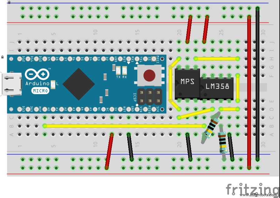 Circuitlab schematic
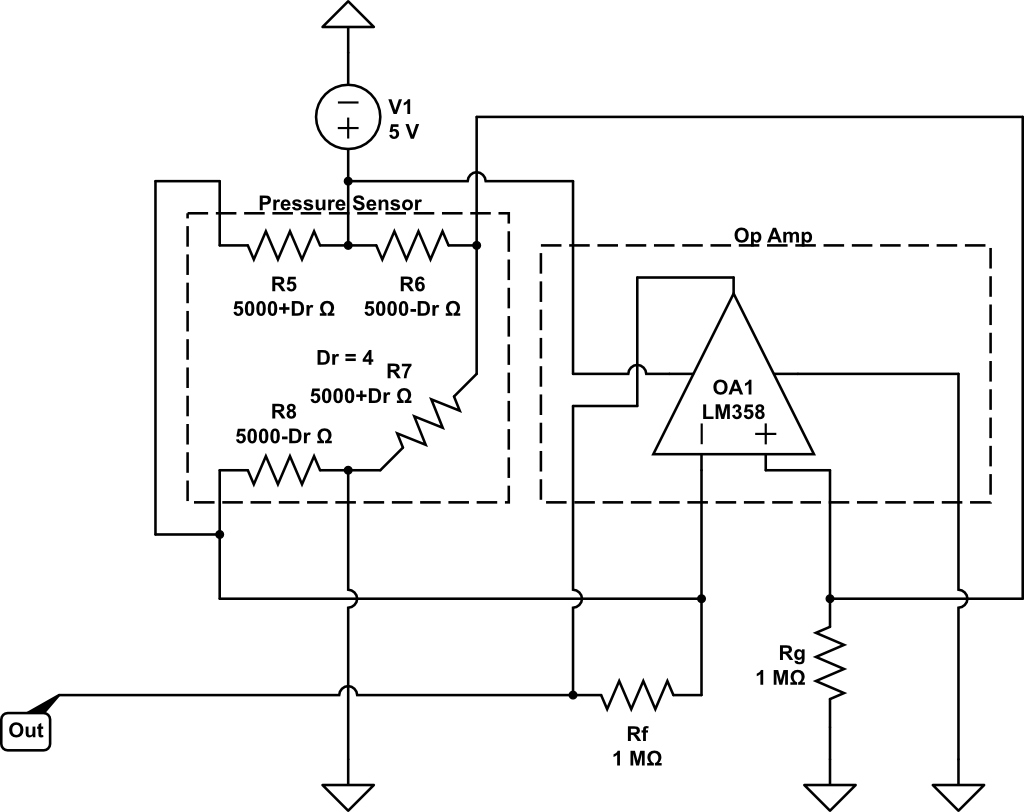
Manufacturing process
- Web‑Controlled DMX Lighting System – Arduino Master Controller
- DIY Arduino USB Gaming Controller – Build Your Own High-Performance Gamepad
- Bluetooth Text Teleporter: Arduino + Android Project
- Arduino‑Based Vacuum Fluorescent Display (VFD) Controller Kit
- Arduino DMX-512 Tester Controller – Full Parts Kit for Reliable Lighting Control
- Precision Joystick Controller for MeArm Robot – Record & Replay Coordinates with Arduino Uno
- Arduino-Driven GrowBox Controller – Open-Source Firmware & Hardware Guide
- Build a Cost-Effective Lightning Detector with Arduino Uno
- Install a Dark Theme in Arduino IDE: Reduce Eye Strain and Enhance Focus
- DIY Low-Cost Laser Rangefinder for Arduino – Quick, Reliable & Affordable