


Exploring MEMS Sensors: Accelerometers, Gyroscopes, and Magnetometers for Arduino Projects
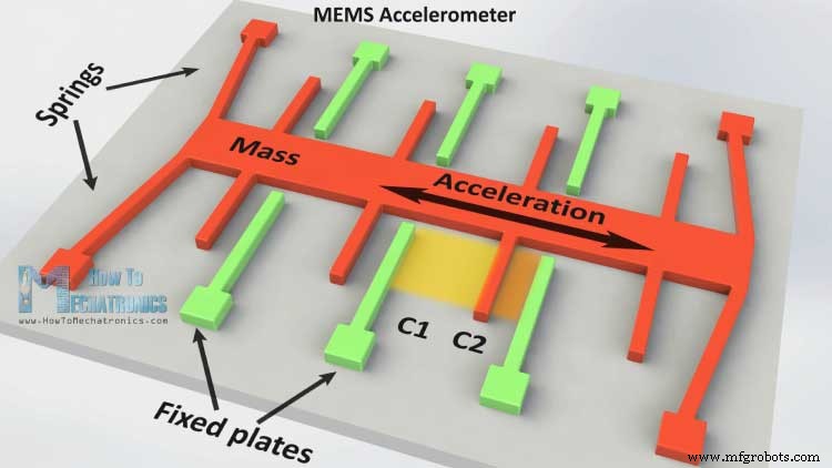
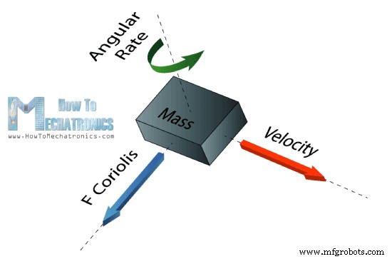
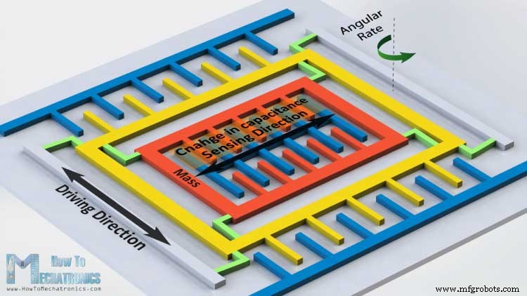
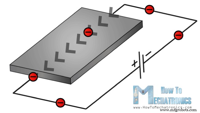
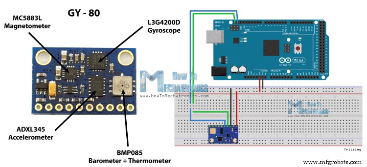
In this tutorial we will learn how the MEMS accelerometer, gyroscope and magnetometer work and how to use them with the Arduino Board. Also with the Processing IDE we will make some practical applications using the sensors. You can watch the following video or read the written tutorial below. The MEMS are very small systems or devices, composed of micro components ranging from 0.001 mm to 0.1 mm in size. These components are made of silicon, polymers, metals and/or ceramics, and they are usually combined with a CPU (Microcontroller) for completing the system. Now we will briefly explain how each of these Micro-Electro-Mechanical-Systems (MEMS) sensors work. It measures acceleration by measuring change in capacitance. Its micro structure looks something like this. It has a mass attached to a spring which is confined to move along one direction and fixed outer plates. So when an acceleration in the particular direction will be applied the mass will move and the capacitance between the plates and the mass will change. This change in capacitance will be measured, processed and it will correspond to a particular acceleration value. The gyroscope measures angular rate using the Coriolis Effect. When a mass is moving in a particular direction with a particular velocity and when an external angular rate will be applied as show with the green arrow a force will occur, as show with the blue red arrow, which will cause perpendicular displacement of the mass. So similar to the accelerometer, this displacement will cause change in capacitance which will be measured, processed and it will correspond to a particular angular rate. The micro structure of the gyroscope looks something like this. A mass that is constantly moving, or oscillating, and when the external angular rate will be applied a flexible part of the mass would move and make the perpendicular displacement. It measures the earth magnetic field by using Hall Effect or Magneto Resistive Effect. Actually almost 90% of the sensors on the market use the Hall Effect and here’s how it works. If we have a conductive plate like shown in the photo and we set current to flow through it, the electrons would flow straight from one to the other side of the plate. Now if we bring some magnetic field near the plate we would disturb the straight flow and the electrons would deflect to one side of the plate and the positive poles to the other side of the plate. That means if we put a meter now between these two sides we will get some voltage which depends from the magnetic field strength and its direction. Ok now let’s connect these sensors to the Arduino Board and make some use of them. As an example I will use the GY-80 breakout board which has the following sensors: ADXL345 3 Axis Accelerometer, L3G4200D 3 Axis Gyroscope, MC5883L 3 Axis Magnetometer and also a Barometer and a Thermometer which we won’t use in this tutorial. You can get these components from any of the sites below: This board use the I2C communication protocol which means that we can use all sensors with just two wires. So in order to make the communication between the Arduino and the sensors we need to know their unique device addresses and their internal register addresses for getting the data out of them. These addresses can be found from the datasheets of the sensors: For more details how the I2C communication works you can check my other I2C Communication Protocol Tutorial. Now let’s see the codes for getting the data from the sensors. We will start with the accelerometer and there will be some explanation before each code, as well as some additional description in the comments of the code . First we need to include the Arduino Wire Library and define the registers addresses of the sensor. In the setup section we need to initiate the Wire Library and start the serial communication as we will use the serial monitor for showing the results. Also here we need to activate the sensor, or enable the measurement by sending appropriate byte to the Power_CTL register and here’s how we do that. Using the Wire.beginTransmission() function we select to which sensor we will talk, the 3-Axis Accelerometer in this case. Then using the Wire.write() function we tell to which internal register we will talk. After this we will send the appropriate byte for enabling the measurement. Using the Wire.endTransmission() function we will end the transmission and that will transmit the data to the registers. In the loop section we need to read the data for each axis. We will start with the X – Axis. So first we will select to which registers we will talk, the two X – Axis internal registers in this case. Then using the Wire.requestFrom() function we will request the transmitted data or the two bytes from the two registers. The Wire.available() function will return the number of bytes available for retrieval and if that number match with our requested bytes, in our case 2 bytes, using the Wire.read() function we will read the bytes from the two registers of the X axis. The output data from the registers is two’s complement, with X0 as the least significant byte and X1 as the most significant byte so we need to convert these bytes into float values from -1 to +1 depending on the direction of the X – Axis relative to the Earth acceleration or the gravity. We will repeat this procedure for the two other axis and at the end we will print these values on the serial monitor. For getting the data from the gyroscope we will have a similar code as the previous one. So first we have to define the register addresses and some variables for the data. In the setup section we have to wake up and put the sensor in normal mode using the CTRL_REG1 and also select the sensitivity of the sensor. For this example I will select the 2000dps sensitivity mode. In the loop section similar to the accelerometer we will read the data for the X, Y and Z axis. Then the raw data has to be converted into angle values. From the datasheet of the sensor we can see that for the 2000dps sensitivity mode corresponds a 70 mdps/digit unit. This means that we have to multiply the raw output data by 0.07 in order to get the angular rate in degrees per second. Then if multiply the angular rate by time it will give us the angle value. So we need to calculate the time interval of each loop section and we can do that by using the millis() function at the top and the bottom of the loop section, and we will store its value into this “dt” variable. So for each executed loop we will calculate the angle and add it to the final angle value. We will do the same for the two other axis and at the end we will print the results in the serial monitor. Again we will use a similar technique to the previous one. First we need to define the registers addresses and it the setup section set the sensor in continuous measurement mode. In the loop section we will get the raw data for each axis with the same method as for the previous sensors. Then we need to convert the raw data into magnetic field value or Gauss units. From the datasheet of the sensor we can see that the default sensitivity mode is 0.92mG/digit. That means we need to multiply the raw data by 0.00092 in order to get the earth magnetic field in Gauss units. At the end we will print the values on the serial monitor. Here’s a cool looking application of the sensor, a MEMS digital compass, made using the Processing IDE. You can find more details and the source code of this example on the following link:What is MEMS?
MEMS Accelerometer
MEMS Gyroscope
MEMS Magnetometer
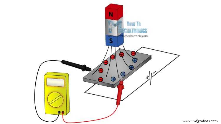
The other 10% of the sensors on the market use the Magneto-resistive Effect. These sensors use materials that are sensitive to the magnetic field, usually composed of Iron (Fe) and Nickel (Ne). So when these materials are exposed to magnetic field they change their resistance.Arduino and MEMs sensors
Source Code
Arduino Accelerometer Code
#include <Wire.h>

//--- Accelerometer Register Addresses
#define Power_Register 0x2D
#define X_Axis_Register_DATAX0 0x32 // Hexadecima address for the DATAX0 internal register.
#define X_Axis_Register_DATAX1 0x33 // Hexadecima address for the DATAX1 internal register.
#define Y_Axis_Register_DATAY0 0x34
#define Y_Axis_Register_DATAY1 0x35
#define Z_Axis_Register_DATAZ0 0x36
#define Z_Axis_Register_DATAZ1 0x37

int ADXAddress = 0x53;  //Device address in which is also included the 8th bit for selecting the mode, read in this case.

int X0,X1,X_out;
int Y0,Y1,Y_out;
int Z1,Z0,Z_out;
float Xa,Ya,Za;

void setup() {
  Wire.begin(); // Initiate the Wire library
  Serial.begin(9600);
  delay(100);

  Wire.beginTransmission(ADXAddress);
  Wire.write(Power_Register); // Power_CTL Register
  // Enable measurement
  Wire.write(8); // Bit D3 High for measuring enable (0000 1000)
  Wire.endTransmission();
}

void loop() {
  // X-axis
  Wire.beginTransmission(ADXAddress); // Begin transmission to the Sensor
  //Ask the particular registers for data
  Wire.write(X_Axis_Register_DATAX0);
  Wire.write(X_Axis_Register_DATAX1);
  Wire.endTransmission(); // Ends the transmission and transmits the data from the two registers
  Wire.requestFrom(ADXAddress,2); // Request the transmitted two bytes from the two registers
  if(Wire.available()<=2) {  //
    X0 = Wire.read(); // Reads the data from the register
    X1 = Wire.read();
    /* Converting the raw data of the X-Axis into X-Axis Acceleration
     - The output data is Two's complement
     - X0 as the least significant byte
     - X1 as the most significant byte */
    X1=X1<<8;
    X_out =X0+X1;
    Xa=X_out/256.0; // Xa = output value from -1 to +1, Gravity acceleration acting on the X-Axis
  }
  // Y-Axis
  Wire.beginTransmission(ADXAddress);
  Wire.write(Y_Axis_Register_DATAY0);
  Wire.write(Y_Axis_Register_DATAY1);
  Wire.endTransmission();
  Wire.requestFrom(ADXAddress,2);
  if(Wire.available()<=2) {
    Y0 = Wire.read();
    Y1 = Wire.read();
    Y1=Y1<<8;
    Y_out =Y0+Y1;
    Ya=Y_out/256.0;
  }
  // Z-Axis
  Wire.beginTransmission(ADXAddress);
  Wire.write(Z_Axis_Register_DATAZ0);
  Wire.write(Z_Axis_Register_DATAZ1);
  Wire.endTransmission();
  Wire.requestFrom(ADXAddress,2);
  if(Wire.available()<=2) {
    Z0 = Wire.read();
    Z1 = Wire.read();
    Z1=Z1<<8;
    Z_out =Z0+Z1;
    Za=Z_out/256.0;
  }
  // Prints the data on the Serial Monitor
  Serial.print("Xa= ");
  Serial.print(Xa);
  Serial.print("   Ya= ");
  Serial.print(Ya);
  Serial.print("   Za= ");
  Serial.println(Za);
}
Code language: Arduino (arduino)
Arduino Gyroscope Code
#include <Wire.h>

//--- Gyro Register Addresses
#define Gyro_gX0 0x28
#define Gyro_gX1 0x29
#define Gyro_gY0 0x2A
#define Gyro_gY1 0x2B
#define Gyro_gZ0 0x2C
#define Gyro_gZ1 0x2D

int Gyro = 0x69; //Device address in which is also included the 8th bit for selecting the mode, read in this case.

int gX0, gX1, gX_out;
int gY0, gY1, gY_out;
int gZ0, gZ1, gZ_out;
float Xg,Yg,Zg;
float angleX,angleY,angleZ,angleXc,angleYc,angleZc;


unsigned long start, finished, elapsed;
float dt=0.015;

void setup()
{
  Wire.begin();
  Serial.begin(9600);
  delay(100);

  Wire.beginTransmission(Gyro);
  Wire.write(0x20); // CTRL_REG1 - Power Mode
  Wire.write(15);   // Normal mode: 15d - 00001111b
  Wire.endTransmission();

  Wire.beginTransmission(Gyro);
  Wire.write(0x23); // CTRL_REG4 - Sensitivity, Scale Selection
  Wire.write(48);   // 2000dps: 48d - 00110000b
  Wire.endTransmission();
}

void loop()
{
  start=millis();
  //---- X-Axis
  Wire.beginTransmission(Gyro); // transmit to device
  Wire.write(Gyro_gX0);
  Wire.endTransmission();
  Wire.requestFrom(Gyro,1);
  if(Wire.available()<=1)
  {
    gX0 = Wire.read();
  }
  Wire.beginTransmission(Gyro); // transmit to device
  Wire.write(Gyro_gX1);
  Wire.endTransmission();
  Wire.requestFrom(Gyro,1);
  if(Wire.available()<=1)
  {
    gX1 = Wire.read();
  }

  //---- Y-Axis
  Wire.beginTransmission(Gyro); // transmit to device
  Wire.write(Gyro_gY0);
  Wire.endTransmission();
  Wire.requestFrom(Gyro,1);
  if(Wire.available()<=1)
  {
    gY0 = Wire.read();
  }
  Wire.beginTransmission(Gyro); // transmit to device
  Wire.write(Gyro_gY1);
  Wire.endTransmission();
  Wire.requestFrom(Gyro,1);
  if(Wire.available()<=1)
  {
    gY1 = Wire.read();
  }

  //---- Z-Axis
  Wire.beginTransmission(Gyro); // transmit to device
  Wire.write(Gyro_gZ0);
  Wire.endTransmission();
  Wire.requestFrom(Gyro,1);
  if(Wire.available()<=1)
  {
    gZ0 = Wire.read();
  }
  Wire.beginTransmission(Gyro); // transmit to device
  Wire.write(Gyro_gZ1);
  Wire.endTransmission();
  Wire.requestFrom(Gyro,1);
  if(Wire.available()<=1)
  {
    gZ1 = Wire.read();
  }

  //---------- X - Axis

  // Raw Data
  gX1=gX1<<8;
  gX_out =gX0+gX1;

  // From the datasheet: 70 mdps/digit
  Xg=gX_out*0.07; // Angular rate
  // Angular_rate * dt = angle
  angleXc = Xg*dt;
  angleX = angleX + angleXc;

  //---------- Y - Axis
  gY1=gY1<<8;
  gY_out =gY0+gY1;
  Yg=gY_out*0.07;
  angleYc = Yg*dt;
  angleY = angleY + angleYc;

  //---------- Z - Axis
  gZ1=gZ1<<8;
  gZ_out =gZ0+gZ1;
  Zg=gZ_out*0.07;
  angleZc = Zg*dt;
  angleZ = angleZ + angleZc;


  // Prints the data on the Serial Monitor
  Serial.print("angleX= ");
  Serial.print(angleX);
  Serial.print("   angleY= ");
  Serial.print(angleY);
  Serial.print("   angleZ= ");
  Serial.println(angleZ);

  delay(10);
  // Calculating dt
  finished=millis();
  elapsed=finished-start;
  dt=elapsed/1000.0;
  start = elapsed = 0;

}Code language: Arduino (arduino)
Arduino Magnetometer Code
#include <Wire.h> //I2C Arduino Library

#define Magnetometer_mX0 0x03
#define Magnetometer_mX1 0x04
#define Magnetometer_mZ0 0x05
#define Magnetometer_mZ1 0x06
#define Magnetometer_mY0 0x07
#define Magnetometer_mY1 0x08


int mX0, mX1, mX_out;
int mY0, mY1, mY_out;
int mZ0, mZ1, mZ_out;

float Xm,Ym,Zm;


#define Magnetometer 0x1E //I2C 7bit address of HMC5883

void setup(){
  //Initialize Serial and I2C communications
  Serial.begin(9600);
  Wire.begin();
  delay(100);

  Wire.beginTransmission(Magnetometer);
  Wire.write(0x02); // Select mode register
  Wire.write(0x00); // Continuous measurement mode
  Wire.endTransmission();
}

void loop(){

  //---- X-Axis
  Wire.beginTransmission(Magnetometer); // transmit to device
  Wire.write(Magnetometer_mX1);
  Wire.endTransmission();
  Wire.requestFrom(Magnetometer,1);
  if(Wire.available()<=1)
  {
    mX0 = Wire.read();
  }
  Wire.beginTransmission(Magnetometer); // transmit to device
  Wire.write(Magnetometer_mX0);
  Wire.endTransmission();
  Wire.requestFrom(Magnetometer,1);
  if(Wire.available()<=1)
  {
    mX1 = Wire.read();
  }

  //---- Y-Axis
  Wire.beginTransmission(Magnetometer); // transmit to device
  Wire.write(Magnetometer_mY1);
  Wire.endTransmission();
  Wire.requestFrom(Magnetometer,1);
  if(Wire.available()<=1)
  {
    mY0 = Wire.read();
  }
  Wire.beginTransmission(Magnetometer); // transmit to device
  Wire.write(Magnetometer_mY0);
  Wire.endTransmission();
  Wire.requestFrom(Magnetometer,1);
  if(Wire.available()<=1)
  {
    mY1 = Wire.read();
  }

  //---- Z-Axis
  Wire.beginTransmission(Magnetometer); // transmit to device
  Wire.write(Magnetometer_mZ1);
  Wire.endTransmission();
  Wire.requestFrom(Magnetometer,1);
  if(Wire.available()<=1)
  {
    mZ0 = Wire.read();
  }
  Wire.beginTransmission(Magnetometer); // transmit to device
  Wire.write(Magnetometer_mZ0);
  Wire.endTransmission();
  Wire.requestFrom(Magnetometer,1);
  if(Wire.available()<=1)
  {
    mZ1 = Wire.read();
  }

  //---- X-Axis
  mX1=mX1<<8;
  mX_out =mX0+mX1; // Raw data
  // From the datasheet: 0.92 mG/digit
  Xm = mX_out*0.00092; // Gauss unit
  //* Earth magnetic field ranges from 0.25 to 0.65 Gauss, so these are the values that we need to get approximately.

  //---- Y-Axis
  mY1=mY1<<8;
  mY_out =mY0+mY1;
  Ym = mY_out*0.00092;

  //---- Z-Axis
  mZ1=mZ1<<8;
  mZ_out =mZ0+mZ1;
  Zm = mZ_out*0.00092;

  //Print out values of each axis
  Serial.print("x: ");
  Serial.print(Xm);
  Serial.print("  y: ");
  Serial.print(Ym);
  Serial.print("  z: ");
  Serial.println(Zm);

  delay(50);
}Code language: Arduino (arduino)
Manufacturing process
- Build a Real-Time Gyroscope Game with Arduino Nano & MPU-6050 Sensor
- Interactive Gyroscope LED Display with NeoPixel Ring and Arduino
- Build a Smart Piggy Bank: Control a Coin Acceptor with Arduino Nano
- Control an LED via Bluetooth with Arduino – Simple DIY Guide
- Accurate Solar Radiation Measurement Using Arduino UNO and Ethernet Shield
- Arduino‑Powered HID UPS: Upgrade Your Dummy Power Supply to USB‑Compatible Backup
- Build a Portable RFID Door Lock with Arduino – Step-by-Step Guide
- Build an IR Sensor Project with Arduino UNO – Simple Guide
- Master the MPU6050: Accelerometer & Gyro Tutorial for Arduino
- Track Orientation with Arduino & ADXL345 Accelerometer – A Step‑by‑Step Guide