


Engineering Tunnels: From Ancient Paths to Modern TBMs and Future Innovations
Background
A tunnel is an underground or underwater passage that is primarily horizontal. Small‑diameter tunnels carry utility lines or serve as pipelines, while larger ones—often used for rail or automobile traffic—feature two or three parallel passages for opposite‑direction flow, service vehicles, and emergency exits.
The world’s longest water‑carrying tunnel stretches 105 mi (170 km) from the Delaware River to New York City. The longest person‑carrying tunnel is Japan’s Seikan Rail Tunnel, 33 mi (53 km) long with a 32‑ft (9.7 m) diameter, linking Honshu and Hokkaido beneath the Tsugaru Strait.
Perhaps the most celebrated modern tunnel is the Channel Tunnel, completed in 1994. It connects Great Britain and continental Europe through three 31‑mi (50 km) tubes—two one‑way and a service tunnel—of which 23 mi (37 km) lie underwater.
History
Ancient civilizations in the Indian and Mediterranean regions hand‑dug tunnels using copper saws, fire, and early rock‑saws. The Babylonian cut‑and‑cover method, developed 4,000 years ago, remains a foundational technique today.
Gunpowder breakthroughs in 1681 produced a 515‑ft (160 m) canal tunnel in France, while the mid‑19th century saw nitroglycerine (dynamite) and steam‑powered drills replace black powder, revolutionizing excavation.
Marc Brunel and James Greathead pioneered the tunneling shield between 1820 and 1865, enabling the construction of two Thames tunnels. Their shield divided the tunnel face into compartments, allowing workers to excavate and support the tunnel incrementally.
In 1873, Clinton Haskins used compressed air to keep water out of a railroad tunnel beneath the Hudson River—a technique still in use, though it demands careful pressure management and decompression chambers for workers.
Soil stabilization has evolved from freezing (coolant circulation) to grouting—injecting liquid bonding agents into surrounding rock. Shotcrete, invented in 1907, has served as both preliminary and final lining since the 1920s.
The 1931 “drilling jumbo” and the 1954 tunnel boring machine (TBM) marked major technological leaps, allowing large, custom‑built machines to cut through rock and soil efficiently.
Raw Materials
Tunnel construction materials vary by design and method. Grouts often contain sodium silicate, lime, silica fume, cement, and bentonite, a volcanic clay that provides absorbency and lubrication. Bentonite‑water slurry facilitates muck removal, while water, salt brine, or liquid nitrogen freeze soft ground. Reinforced concrete—sprayed, cast in place, or prefabricated—is the most common lining.
Choice of Method
Selection depends on geology, cost, and disruption potential. Multiple methods can coexist within a single project; for example, Boston’s Central Artery/Tunnel employs four distinct techniques across different sections.
The Manufacturing Process
Preparing
- Site geology is assessed through surface surveys and core sampling. A pilot tunnel—typically one‑third the diameter of the main tunnel—is often built along the route to test geology and construction methods, providing ventilation, service access, and emergency exits.
- Soil stabilization may involve grouting via small pipes or freezing by circulating refrigerants through embedded pipes.
Mining
- Immersed Tube Method: Steel or reinforced concrete sections are fabricated on land, floated to the site, anchored, and sunk into a pre‑dug trench, then connected with rubber seals.
- Cut‑and‑Cover: A trench is excavated, a box‑shaped tunnel is cast in place, and the trench is then covered with soil. In sensitive soils, steel sheets or slurry walls pre‑support the trench.
- Top‑Down: Parallel walls are built first, then the roof is poured and cured. Excavation proceeds beneath the roof, with a waterproof membrane protecting the finished shell.
- Drill‑and‑Blast: Patterned holes are drilled, dynamite charges are set, and controlled blasts break the rock. Air circulation clears dust and gases, and pneumatic drills finish the surface.
- Shield/Greathead: A shield advances incrementally, with workers excavating ahead and then pushing the shield forward using jacks. Permanent lining rings are installed immediately after the shield moves.
- Parallel Drift: Microtunneling creates horizontal drifts, which are then grouted or lined to form a protective arch around the main tunnel path.
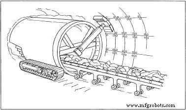
- Tunnel Boring Machine (TBM): A custom‑built machine with a rotating cutter head grinds rock or soil, advancing with the aid of jacks or gripper arms. Muck is conveyed out, while bentonite is pumped to lubricate the face. Some TBMs install lining segments or use the New Austrian Tunnelling Method (NATM) for preliminary support.
Final Lining
- During excavation, TBMs may install lining segments or prefabricated tunnels are jacked into place.
- After excavation, a reinforced concrete lining can be poured in place using slipforming—moving a form continuously as concrete cures.
- Alternatively, prefabricated concrete or steel segments are bolted into a ring, then grouted.
- Shotcrete can be sprayed several inches thick, optionally reinforced with wire mesh or fibers for added strength.
Byproducts/Waste
Excavated material is either disposed of in landfills or repurposed—forming the base course for approach roads, creating embankments, or serving as erosion control material.
Quality Control
Maintaining ground stability, structural integrity, and precise alignment is critical. GPS sensors provide satellite‑based positional data, while laser guidance systems project and detect beams to ensure accurate excavation paths.
The Future
Advances in exploration, materials, and machinery promise significant improvements. Sonic imaging now generates virtual CAT scans of tunnel paths, reducing the need for core sampling. Research focuses on high‑performance cutting tools, self‑regulating concrete, and soil‑modifying agents. Cutting‑edge TBMs can bore multiple tunnels simultaneously or navigate turns up to 90° while cutting, and remote control reduces worker exposure underground.
Notable Projects
 The Channel Tunnel, completed in 1994 at a cost of $13 billion, connects England and France. The two rail tunnels and one service tunnel are each 31 mi (50 km) long and average 150 ft (46 m) below the seabed. Passenger rail service and vehicle transport now reduce London‑to‑Paris travel from five hours over sea to three hours through the tunnel.
The Seikan Tunnel, opened in 1988, spans 33 mi (53 km) beneath the Tsugaru Strait, making it the world’s longest submarine tunnel. It sits 330 ft (100 m) below the seabed, traversing a strait up to 460 ft (140 m) deep.
Manufacturing process
- Engineering Tunnels: From Ancient Paths to Modern TBMs and Future Innovations
- Preventing Tunnel Vision: A Proactive Approach to Plant Safety and Reliability
- High‑Performance Analog/RF T‑Shaped Gate Dual‑Source Tunnel Field‑Effect Transistor
- Ultrathin Al₂O₃ Layers Enhance Mg‑Doped LiNbO₃ Film Reliability and Fatigue Endurance
- Modulating Magnetization Dynamics via Dzyaloshinskii-Moriya Interaction in Double-Interface STT Magnetic Tunnel Junctions
- Step-Thickness Design Boosts DG TFET Efficiency: A Simulation Study
- Intelligent Disinfection Tunnel: Automated Sanitization for High‑Traffic Areas
- Expert Guide to Godown Wiring Circuits in Tunnels & Warehouses
- Professional Tunnel Lighting Control Circuit Diagram Using SPDT Switches
- Enhance Injection-Molded Parts with Tunnel Gates: Expert Design Tips