


FPGA Implementation Languages: From VHDL and Verilog to High‑Level C/C++
 Editor’s Note: Advanced algorithms in smart products demand embedded systems that can handle heavy processing loads. FPGAs deliver the performance needed, yet many developers view FPGA design as the domain of specialists. Modern hardware, coupled with powerful development environments, has democratized FPGA programming. This excerpt from Chapter 4 of *Architecting High‑Performance Embedded Systems* offers a thorough overview of FPGA devices, the languages used to implement them, and the development workflow, culminating in a practical guide to start building your own FPGA designs.
1: Hardware resources
2: Implementation languages (this article)
3: Development process
4: Building a project
5: Implementation
Adapted from *Architecting High‑Performance Embedded Systems*, by Jim Ledin.
FPGA Implementation Languages
Designing for an FPGA ultimately involves selecting one or more high‑level, HDL‑like languages to describe the device’s behavior.
Traditional choices are VHDL and Verilog. Modern toolchains typically support both, plus block‑diagram configuration, and many now accept C/C++ as a source for automatic HDL generation.
VHDL
VHSIC Hardware Description Language (VHDL)—VHSIC standing for *Very High‑Speed Integrated Circuit*—was developed under the U.S. Department of Defense in 1983. Its syntax is reminiscent of Ada, which makes it verbose and strongly typed. The language offers a fixed set of base types such as boolean, bit, bit_vector, character, string, integer, real, time, and array, with all other types built upon these primitives.
IEEE 1164 defines the standard library for VHDL, including the ubiquitous std_logic type that represents a single‑bit signal. The following table shows the logic values for std_logic:
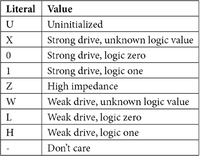
Strong 0/1 denote driven binary states, while weak signals indicate contention on a bus. Z represents high‑impedance (CMOS output disconnected), U is the default uninitialized state, X indicates no driver, and - marks unused inputs.
Typical VHDL designs start by importing the IEEE 1164 library:
library IEEE;
use IEEE.std_logic_1164.all;
In this chapter we’ll use VHDL as an example, but both VHDL and Verilog can fully express any FPGA‑synthesizable design.
Verilog
Introduced in 1984 and standardized as IEEE 1364 (2005), Verilog was modeled after C to make the learning curve gentler. In 2009 it merged with SystemVerilog to form IEEE 1800‑2009, adding extensive verification features on top of core HDL constructs.
Verilog’s wire type represents signal states of 0, 1, don’t‑care (x), or high‑impedance (z), each with a strong or weak strength. Both VHDL and Verilog have *synthesizable* subsets for hardware design, while additional constructs support simulation.
For example, a non‑synthesizable for loop behaves like a software loop, iterating sequentially. A synthesizable for loop is unrolled into parallel hardware copies, mirroring the iteration count.
Block Diagrams
Beyond textual HDLs, modern FPGA suites provide graphical block‑diagram editors that let designers assemble complex systems—such as microprocessors and advanced I/O—without writing low‑level code. Figure 4.2 illustrates a Xilinx Vivado block diagram featuring a MicroBlaze soft processor.
click for full size image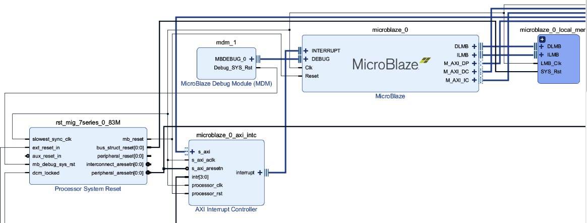
Figure 4.2 – Block diagram containing a MicroBlaze soft microprocessor
The MicroBlaze is Xilinx’s soft‑core processor available for Artix‑7 and other families. While block diagrams simplify system layout, the tool ultimately generates VHDL or Verilog behind the scenes. Inspecting the generated code—e.g., design_1_microblaze_0_0_stub.vhdl—reveals the HDL entity interface:
library IEEE;
use IEEE.STD_LOGIC_1164.ALL;
entity design_1_microblaze_0_0 is
Port (
Clk: in STD_LOGIC;
Reset: in STD_LOGIC;
Interrupt: in STD_LOGIC;
Interrupt_Address: in STD_LOGIC_VECTOR (0 to 31);
Interrupt_Ack: out STD_LOGIC_VECTOR (0 to 1);
Instr_Addr: out STD_LOGIC_VECTOR (0 to 31);
Instr: in STD_LOGIC_VECTOR (0 to 31);
Note that this file defines only the processor’s interface; the core logic is supplied as licensed IP, often in compiled form to protect intellectual property.
C/C++
Several vendors now provide high‑level synthesis (HLS) tools that translate C or C++ into HDL, enabling developers to port existing algorithms to FPGA hardware. While the underlying FPGA runs in parallel, the generated design often maps sequential C/C++ statements into state machines. Where the source code offers opportunities for parallelism, the FPGA can deliver significant speedups over a conventional processor.
Modern toolchains allow VHDL, Verilog, block diagrams, and HLS‑derived HDL to coexist within a single project. Teams may mix languages based on skill sets, but careful planning is essential to avoid maintenance overhead and ensure future sustainment.
In the next section we’ll walk through the standard FPGA development process, from concept to implementation.
Reprinted with permission from Packt Publishing. Copyright © 2021 Packt Publishing
 Jim Ledin is the CEO of Ledin Engineering, Inc. Jim is an expert in embedded software and hardware design, development, and testing. He is also accomplished in embedded system cybersecurity assessment and penetration testing. He has a B.S. degree in aerospace engineering from Iowa State University and an M.S. degree in electrical and computer engineering from Georgia Institute of Technology. Jim is a registered professional electrical engineer in California, a Certified Information System Security Professional (CISSP), a Certified Ethical Hacker (CEH), and a Certified Penetration Tester (CPT).
Related Contents:
- Embedded design with FPGAs: Hardware resources
- Open‑source tools help simplify FPGA programming
- Implementing floating‑point algorithms in FPGAs or ASICs
- Software tools migrate GPU code to FPGAs for AI applications
- FPGAs displace ASICs in Subaru Eyesight vision‑based ADAS
- How flash‑based FPGAs simplify functional safety requirements
- Reaping the benefits of instant‑on FPGAs
- FPGA configuration using high‑speed NOR flash
- How FPGA technology is evolving to meet new mid‑range system requirements
For more Embedded, subscribe to Embedded’s weekly email newsletter.
Embedded
- Embedded System Programming: Languages, Architecture, and Applications
- Embedded System Design: Steps, Principles, and Real‑World Applications
- High‑Performance FPGA Accelerator for Embedded Vision with MIPI Cameras
- FPGA Hardware Resources for High‑Performance Embedded Systems
- Getting Started with FPGA Development: Building a 4‑Bit Adder on Xilinx Artix‑7
- Embedded FPGA Design: A Complete Development Process
- Mastering FPGA Embedded Design: A Practical Implementation Guide
- Embedded FPGA (eFPGA) Technology: Revolutionizing ASIC and SoC Design
- Streamline Electrical Harness Design with E3.series
- Maximizing Production with Advanced Additive Manufacturing Software