


Understanding JTAG and Arm Core Debugging: ADI and SWD Explained
This article demystifies how JTAG is integrated into ARM core devices, focusing on the Arm Debug Interface (ADI) and the Serial Wire Debug (SWD) protocol.
Previous posts in this series explored the IEEE 1149.1 standard, the Test Access Port (TAP) controller, and the TAP state machine. We also reviewed common JTAG pinouts, connectors, and the array of market‑available debug probes.
Here we pivot to the ARM ecosystem, detailing how the ubiquitous ARM core processors implement JTAG through ADI and its two‑wire SWD variant.
What Is ARM?
ARM denotes a processor architecture and a vast portfolio of intellectual property that defines microprocessor and microcontroller interfaces. While consumer PCs typically use x86, embedded systems almost exclusively rely on ARM cores.
Core intellectual property is licensed to silicon manufacturers—such as STMicroelectronics, NXP, and others—who then add peripheral features (I²C, SPI, ADC/DAC, USB, etc.). ARM architectures are versioned (ARMv2, ARMv6, ARMv7, ARMv8, etc.), and the cores are branded as ARMx (e.g., ARM7) or, more recently, as Cortex‑A/R/M series for application, real‑time, and microcontroller use cases. Architecture versioning follows the Cortex suffix, yielding names like ARMv7‑A or ARMv6‑M.
Debugging in ARM is governed by the CoreSight architecture, which encompasses the Arm Debug Interface (ADI), Embedded Trace Macrocell (ETM), High‑Speed Serial Trace Ports (HSSTP), and program‑flow trace. The ADI provides the foundation for debugging, offering both a JTAG interface and the Serial Wire Debug (SWD) alternative.
Arm Debug Interface (ADI) Overview
The ADI specification defines both the hardware and logical interfaces between a host debugger and one or more ARM devices. Most contemporary processors support ADIv5 (Arm IHI0031E), while ADIv6 (Arm IHI0074C) is being adopted gradually. We focus on ADIv5 here.
ADI introduces the Debug Access Port (DAP), composed of a Debug Port (DP) and one or more Access Ports (APs). The DP manages the physical connection (JTAG or SWD) and contains built‑in registers; APs provide access to system resources such as debug registers, trace ports, ROM tables, or system memory.
ADI supports two DP types: JTAG‑DP and SWD‑DP. APs come in three flavors: MEM‑AP (memory‑mapped access), JTAG‑AP (scanning entire debug unit), and vendor‑specific APs. MEM‑APs are the most common.
In the context of JTAG, ADIv5 supplies a set of instruction codes (e.g., EXTEST, SAMPLE, PRELOAD, INTEST, CLAMP, HIGHZ, ABORT, DPACC, APACC, IDCODE, BYPASS) and data registers (ABORT, DPACC, APACC, IDCODE, BYPASS). Notably, DPACC and APACC allow the debugger to issue commands to the DP and AP registers, respectively.
Typical DP registers include:
- CTRL/STAT – controls and reports DP status.
- DLCR – Data Link Control, setting link mode.
- DLPIDR – Data Link Protocol ID, indicating protocol version.
- DPIDR – Debug Port Identification.
- EVENTSTAT – signals events to the external debugger.
- RDBUFF – Read Buffer for DP operations.
- SELECT – selects an AP and its register bank.
- TARGETID – identifies the target when only one device is connected.
MEM‑AP registers include:
- CSW (0x00) – Control/Status Word.
- TAR (0x04) – Transfer Address Register.
- DRW (0x0C) – Data Read/Write register.
- BD0–BD3 (0x10–0x1C) – Banked Data registers.
- CFG (0xF4) – Configuration.
- BASE (0xF8) – Debase Base Address.
- IDR (0xFC) – Identification Register.
Figure 1 illustrates the ADI wiring and register map (not all registers are shown for brevity).
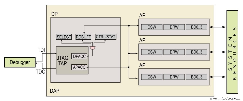
Figure 1. Arm Debug Interface diagram, summarizing connections. Not all DP/AP registers are depicted.
Serial Wire Debug (SWD)
SWD is ARM’s two‑wire JTAG alternative, designed for devices with limited pin counts. Many Cortex‑M microcontrollers employ SWD instead of full JTAG to conserve pins.
SWD replaces the JTAG TDI/TDO pair with a single bidirectional SWDIO pin, eliminates the TMS pin, and retains the clock (re‑labelled SWCLK). Because SWD omits the TAP state machine, commands are sent serially over SWDIO and then the same pin is used for data transfer.
Communication proceeds in three phases: packet request, acknowledgment, and data transfer. A parity bit is used throughout. The sequence begins with a Start bit (HIGH), followed by the AP/D P bit, RnW bit, address bits, parity, Stop bit (LOW), and Park bit. After the request, the target replies with a 3‑bit ACK. For writes, the host transmits 32 bits of data (least‑significant bit first) with a parity bit; for reads, the target drives 32 bits of data back to the host.
Figure 2 presents the timing diagram for read and write operations.
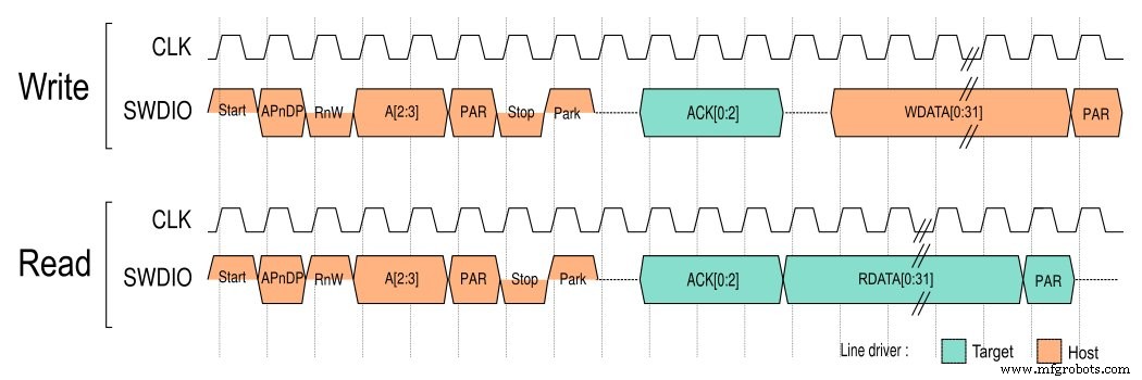
Figure 2. Timing diagrams for Serial Wire Debug read and write operations. Click to enlarge.
Two SWD versions exist: SWDv1 (point‑to‑point) and SWDv2 (single‑host, multi‑target). Version 2 is largely backward compatible with minor edge‑case differences.
Other Reduced‑Pin JTAG Variants
Beyond SWD, the IEEE 1149.7 standard defines a two‑wire JTAG interface. Additional IEEE 1149.x standards (1149.4 for mixed‑signal test, 1149.6 for advanced digital networks) provide extended capabilities such as analog boundary‑scan and differential AC‑coupled lines.
Updated standards can be found on the IEEE Standards Association website.
Conclusion
We’ve traced JTAG’s origins, examined its physical implementation, and explored how ARM core processors adapt JTAG via the ADI and SWD protocols. Armed with this knowledge, engineers can confidently debug and program embedded devices, selecting the appropriate interface for their hardware constraints.
Embedded
- Inductors Explained: Types, Functions, and Applications
- Quantum Devices: Beyond CMOS – Harnessing Tunneling, Quantum Dots, and Spintronics for Future Electronics
- Makerarm: The All‑in‑One Desktop Robotic Arm for Makers
- Real‑Time Software Tracing for Field‑Deployed IoT Devices
- Reliable Power‑On Solutions for Battery‑Operated Medical Devices
- Tracking Advancements in Medical Device Technology
- Renesas Launches Ultra‑Compact 8.2‑mm Creepage Photocouplers to Shrink Industrial Automation and Solar Inverter Designs
- Arm Introduces Cortex‑M55 & Ethos‑U55: New IP Cores Empowering TinyML on Low‑Power Endpoints
- Infineon Unveils IMC300 Motor Controller with Integrated Arm Cortex‑M0 for Enhanced Flexibility
- Five Key Components of Industrial Robot Arms