


Linear Variable Differential Transformers (LVDTs): Fundamentals, Design, and Key Performance Metrics
Explore the core principles of LVDTs: structure, operation, transfer function, linear range, linearity, and sensitivity.
The linear variable differential transformer (LVDT) is a precision electromechanical transducer that converts mechanical core displacement into a proportional AC voltage. It delivers virtually infinite resolution, sub‑0.5% linearity, high sensitivity, and virtually no mechanical friction, making it ideal for critical measurement applications.
In this article we detail the physical layout, working principles, and three critical performance parameters—linear range, linearity error, and sensitivity.
Structure of an LVDT
Figure 1 illustrates a typical LVDT cut‑away and its equivalent circuit. The device consists of a single primary winding surrounded by two secondary windings. A ferromagnetic core, usually a non‑ferrous rod, is free to move along the axis of the coils. As the core shifts, the magnetic coupling to each secondary changes, producing position‑dependent voltages.
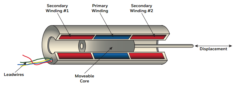
Figure 1(a). Cut‑away view of an LVDT. Image courtesy of Honeywell
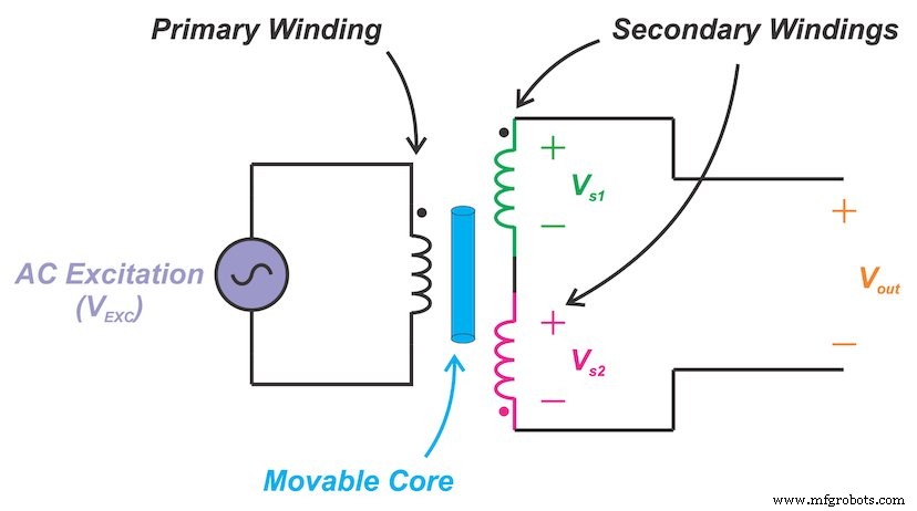
Figure 1(b). Circuit model of an LVDT
The two secondary windings are series‑opposed: they are connected in series but wound in opposite directions. The core attaches to the measured object; the coil assembly remains stationary.
How It Works
When the core sits at the center, equal magnetic flux links both secondaries. Because the secondaries are wound oppositely, their induced voltages cancel, yielding zero output voltage (Vout = 0). This is shown in Figure 2.
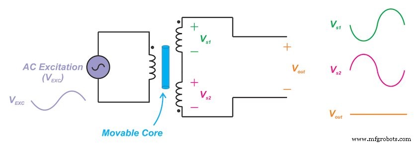
Figure 2. LVDT with a perfectly centered core
Displacing the core upward strengthens the coupling to the first secondary, creating a larger voltage there than in the second secondary (|Vs1| > |Vs2|). The resulting output is non‑zero and in phase with the excitation, as illustrated in Figure 3.
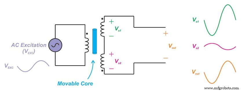
Figure 3. LVDT with the core moved upward
Conversely, a downward core shift favors the second secondary, producing a negative output that is ideally 180° out of phase with the excitation. The waveforms for this scenario are shown in Figure 4.
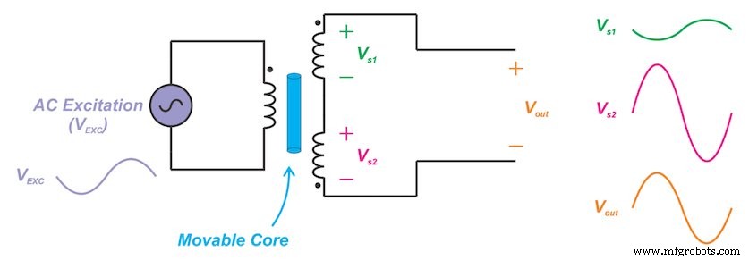
Figure 4. LVDT with the core moved downward
Transfer Function
The relationship between core displacement and output voltage is captured in Figure 5. The transfer curve is linear around the null point, but only within a limited displacement range.
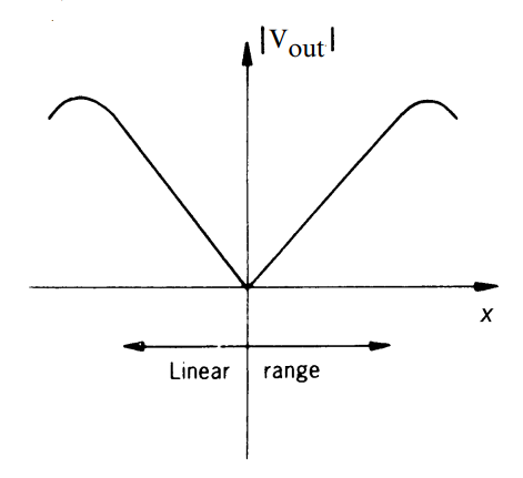
Figure 5. Image courtesy of Ramón Pallàs‑Areny and John G. Webster, Sensors and Signal Conditioning
Measuring only amplitude cannot indicate the direction of displacement; phase information is essential to resolve left versus right movement.
Linear Range
Beyond the linear region, the magnetic coupling saturates and the output deviates from the straight‑line trend. The maximum displacement over which the output remains linear is defined as the full‑scale range. LVDTs are available from ±100 µm up to ±25 cm, suitable for laboratory, industrial, and submersible use.
Linearity Error
Even within the nominal linear range, the output curve is not perfectly straight. The greatest deviation from the best‑fit line is termed the linearity error, typically expressed as a percentage of full‑scale output. For example, the Measurement Specialties E‑100 LVDT lists a ±0.5 % linearity error.
Magnetic saturation can introduce a third‑harmonic component even at null; this can be mitigated with a low‑pass filter on the output.
Sensitivity
Sensitivity—or transfer ratio—relates output voltage to core displacement. With the primary energized at its recommended level (3 VRMS for the E‑100), the core is moved by the full‑scale displacement. The resulting output voltage yields the sensitivity via:
\[\text{Sensitivity} = \frac{V_{out}}{V_{Primary}\times\text{Core Displacement}}\]
Typical units are millivolts output per volt of excitation per thousandth of an inch of core displacement (mV/V/mil). The E‑100 offers 2.4 mV/V/mil, enabling designers to size the conditioning amplifier accurately.
In summary, LVDTs combine high resolution, excellent linearity, and zero mechanical friction, making them a cornerstone transducer for precise displacement measurement across a broad range of applications.
Sensor
- Verilog Basics: Designing Your First AND Gate
- Continuous Hinges (Piano Hinges): Design, Function, and Applications
- Foundations and Advancements of AC Motor Technology
- The Evolution and Production of Action Figures
- Understanding Battery Management Systems (BMS): Core Concepts and Key Components
- Understanding Variables in C: Types, Naming Rules, and Memory Management
- Computing Symbolic Derivatives in MATLAB with the diff Command
- Smartwatch Alerts Athletes to Heat Strain Risks Using Real-Time Core Temperature Monitoring
- Center‑Tapped Transformers Explained: How They Work and Where They’re Used
- Fanuc G72.2 Linear Copy: Efficient Figure Duplication on CNC Mills