


Conventional vs. Electron Flow: What Engineers Use and Why
"The nice thing about standards is that there are so many of them to choose from." —Andrew S. Tanenbaum, computer science professor
Positive and Negative Electron Charge
Benjamin Franklin’s early experiments with static electricity led him to postulate that charge moved from smooth wax to rough wool. Although we now know that electrons – the true carriers of charge – travel from the wool to the wax, the terminology stuck. Because Franklin assumed the opposite direction, the terms “positive” and “negative” were applied inversely, so electrons carry a negative charge even though they represent a surplus of charge.
When the true direction of electron flow was later clarified, the established vocabulary remained unchanged. The labels “positive” for a surplus of charge and “negative” for a deficiency are human conventions, not physical absolutes. One could have chosen any other pair of colors or symbols – the important point is consistency.
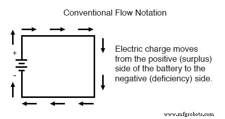
Conventional Flow Notation
Engineers continued to use the familiar + and – symbols to describe the movement of charge, assigning + to a surplus and – to a deficiency. This approach, known as conventional flow, aligns the direction of current arrows with the perceived sign of the charge, even though electrons actually move in the opposite direction.
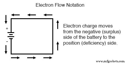
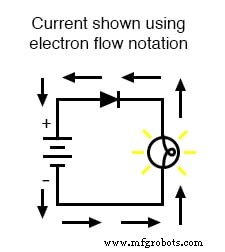
Electron Flow Notation
Alternatively, one can diagram the actual motion of electrons, labeling the direction of current with the opposite sign. This method is called electron flow notation.
Both conventions are mathematically equivalent. Whether you follow the imagined direction of conventional current or the real direction of electron motion, voltage, resistance, continuity, Ohm’s Law, and Kirchhoff’s Laws hold true. The choice is a matter of tradition and clarity.
Conventional vs. Electron Flow in Practice
Conventional flow dominates electrical engineering literature and industry schematics. Electron flow is more common in introductory texts and among solid‑state physicists who focus on the microscopic behavior of charge carriers.
Because most circuit analyses do not depend on the physical direction of electrons, the preference for one notation over the other is largely cultural. Engineers often adopt the convention that best facilitates communication and reduces confusion.
Polarization and Non‑Polarization
Devices that operate identically regardless of current direction – such as incandescent lamps, most conductors, and switches – are considered non‑polarized. Conversely, a polarized component behaves differently when current flows in opposite directions.
Polarized devices, particularly semiconductors, are represented in schematics with an arrow indicating the preferred current direction. Because the electrical engineering community settled on conventional flow, these arrows point from + to – – the opposite of the actual electron path.
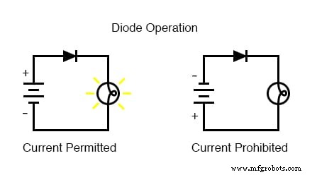
The Diode: A Classic Polarized Device
A diode acts like a one‑way valve for electric current. When oriented correctly, it offers negligible resistance in the forward direction and blocks current in reverse.

In a simple battery‑lamp circuit, the diode allows current to pass and the lamp to glow only when the diode’s forward direction aligns with the conventional current arrow.
Using conventional flow, the diode’s arrow points in the direction of charge flow, making the schematic intuitive:
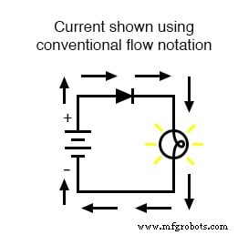
With electron flow, the arrow appears reversed, which can be confusing for those accustomed to conventional diagrams:
Which Notation Should You Use?
Both notations are valid as long as you apply them consistently. In electrical engineering, conventional current is overwhelmingly preferred because it aligns with established symbols and industry practice. Students and professionals who study electronics should become comfortable thinking of current as flowing from higher to lower voltage.
RELATED WORKSHEETS:
- Electron Versus Conventional Flow Worksheet
Industrial Technology
- Understanding Electron Tubes: Components and Functionality
- Decimal vs. Binary Numeration: Place‑Weight, Efficiency, and Conversion
- Numbers vs Numeration: Understanding the Distinction and Its Practical Impact
- Understanding Data Flow: From Simplex to Full‑Duplex Communication
- From Electric to Electronic: The Evolution of Control in Circuits
- Active vs. Passive Electronic Components: Understanding Their Roles
- A Primer on Vacuum (Electron) Tubes: Foundations of Modern Electronics
- Tubes versus Semiconductors: When Vacuum Tubes Still Outshine Solid‑State Devices
- Understanding Conductors, Insulators, and the Science of Electron Flow
- Full-Suspension vs Conventional Haulers: 3 Must-Know Factors for Operators