


DIY Dual‑Axis FPV Camera Cradle: Arduino‑Controlled Joystick Tutorial
Components and supplies
 |
| × | 1 | |||
|
| × | 2 |
About this project
Hello everyone,
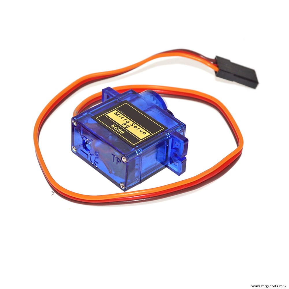
Today we gonna see the full tutorial on how to control the 2-Axis FPV camera cradle with joystick module, the camera cradle comes in a little package containing some acrylic supports and pieces, some screws and two servo motors.
Requirement: So please before you proceed, if you’re not familiar with the joystick, neither the servo motors, here are two tutorials for you:
- How to simply interface the Joystick module with Arduino board
- Use servo motors with Arduino
So here we’ll use two methods to control the servos: the first one where the servos follow the position of the joystick and they move while we move our stick, the second one the servos start moving toward the direction where the joystick is pointing and they stay there until we move the stick again or change direction.
This is a demo of what we gonna have at the end:
In the tutorial video I went step by step while wiring or calibrating also step by step while coding, but here I’ll give you the whole wiring which is not a problem because no module or servo is affecting the others.
To not be confused by the joystick axis my joystick has (X axis on top then Y axis) here in the picture they are inverted and named otherwise but I let the wiring as I used you can change it as you like (servo pins, joystick inputs, directions …)
So not to confuse you because I’ve actually used a lot of codes in the video, but they are very basic (servo positionning, reading analog value from joystick…) I’ve did this before you can check my other tutorials, so here I’ve only uploaded the two codes for the two final versions as seen in the video.
If you need anything about this you can contact me.
Code
- Code 1 as in video
- Code 2 as in video
Code 1 as in videoArduino
//This code is to use with dual axis fpv camera cradle that uses two servos, adding a joystick module
//we control the position of the cradle by moving the analog stick, the cradle follows the joystick movements
//Refer to surtrtech.com for more information

#include <Servo.h> //Servos library and declaration

Servo myservo1;
Servo myservo2;

int YAxis = 1; //Declaring where the X axis and Y axis of the joystick pins are wired
int XAxis = 0; //Of course analog inputs

void setup() {
 Serial.begin(9600); //Setting the Serial monitor baude rate and launching
 pinMode(XAxis, INPUT); //Declaring the pin modes and servo pins
 myservo1.attach(8);
 pinMode(YAxis, INPUT);
 myservo2.attach(9);

}
void loop() {
 int X=analogRead(XAxis); //Reading from the X axis potentiometer
 X=X*0.1756; //Converting the range of the potentiometer from 0-1023 to 0-180 limits of the servo you can change them if you have a 360° servos
 X=180-X;// This is used so the servo turn to exact position otherwise it will be inverted
 myservo1.write(X); //After adapting we inject that value to the first servo

 int Y=analogRead(YAxis);//Reading from the Y axis potentiometer
 Y=Y*0.1466; //Here we did conversion that suits the servo limits so we went from 0-1023 to 0-150
 myservo2.write(Y);//And we inject to our servo
}
Code 2 as in videoArduino
//This code is to use with dual axis fpv camera cradle that uses two servos, adding a joystick module
//We control the position of the cradle by moving the analog stick, the cradle move to the direction where the stick is pointing
//until the limits and stay there
//Refer to surtrtech.com for more information

#include <Servo.h> //Servos library and declaration

Servo myservo1;
Servo myservo2;

int a,b,X,Y; //Variables needed later
int YAxis = 1; //Declaring where the X axis and Y axis of the joystick pins are wired
int XAxis = 0; //Of course analog inputs

void setup() {
 Serial.begin(9600); //Setting the Serial monitor baude rate and launching
 pinMode(XAxis, INPUT); //Declaring the pin modes and servo pins
 myservo1.attach(8);
 pinMode(YAxis, INPUT);
 myservo2.attach(9);
}

void loop() {

 a=myservo1.read(); //Reading the previous servos positions is an important step so we can know where they should position next
 b=myservo2.read();
 X=analogRead(XAxis);//Reading the joystick values
 Y=analogRead(YAxis);

 if(X>550){ //Here we didn't do any calibration so the joystick has three positions (Left|Resting|Right)
 a=a-1; //it depends on the value we read we can know in which direction the stick is pointing and I left the resting position big actually it's just 1 value
 myservo1.write(a); //we inject the new value
 delay(50); //You can make the delay big or short or act on a=a-x to make big steps or short steps
 }
 if(X<450){
 a=a+1; //Here we did the opposit operation to move to the opposit direction
 myservo1.write(a);
 delay(50);
 }
 if(Y>600){ //Here we didn't do any calibration so the joystick has three positions (Up|Resting|Down) ditto
 b=b+1;
 myservo2.write(b);
 delay(50);
 }
 if(Y<450){
 b=b-1;
 myservo2.write(b);
 delay(50);
 }
Schematics
There is a top servo and bottom servo don't get them confused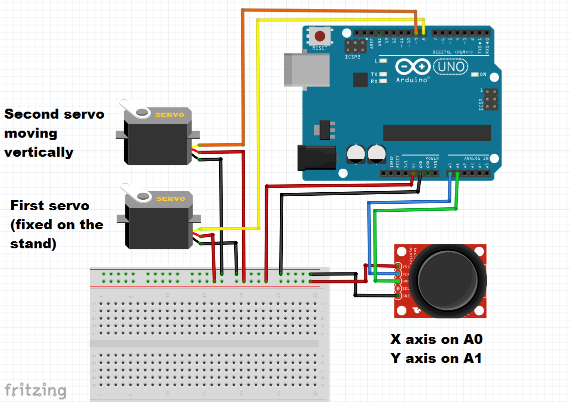
Manufacturing process
- Installing a Raspberry Pi Camera in a Birdhouse – Step‑by‑Step Guide
- Build a Smart Piggy Bank: Control a Coin Acceptor with Arduino Nano
- Control an LED via Bluetooth with Arduino – Simple DIY Guide
- Control Two Stepper Motors with Arduino Nano & Joystick – Simple Tutorial
- Precise Stepper Motor Control: 28BYJ-48 with Arduino UNO & Joystick
- Dual-Axis Solar Tracker with Auto & Manual Control – Efficient Sun‑Tracking System
- Display Numbers on a 7‑Segment Display Using a Keypad – Step‑by‑Step Guide
- AI‑Powered Camera System for Accurate Cap Crack Detection in High‑Speed Production Lines
- Master Arduino Servo Motor Control: Step‑by‑Step Guide
- Hurco TM8 Slant-Bed Lathe – Compact Design, Precision Control & Versatile Tooling