


8051‑Based Ultrasonic Distance Sensor – Design, Circuit, and Applications
Ultrasonic sensors are indispensable for precise, contact‑less distance measurement, finding applications in robotics, parking assistance, and security systems. This article details a complete ultrasonic object‑detection circuit that runs on an 8051 microcontroller, covering hardware, software, and real‑world uses.
Ultrasonic Object‑Detection Circuit
The circuit detects an object in front of the transducer. The transducer emits a 40 kHz pulse; the receiver converts the reflected echo into an electrical signal that the microcontroller processes as a variable‑width pulse.
Block Diagram of the Object‑Detection System
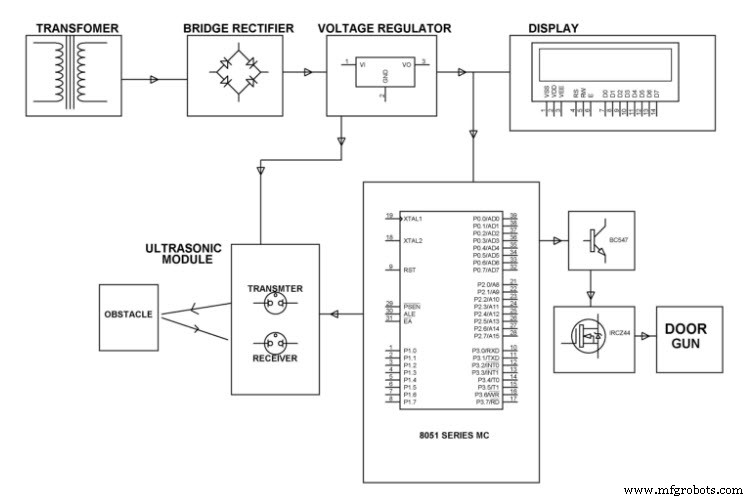
Hardware Requirements
- Ultrasonic sensor module (HC‑SR04 or equivalent)
- 8051 microcontroller (40‑pin DIP, 5 V operation)
- LCD display for status output
- LED indicator for active measurement
- Crystal oscillator (12 MHz, 30 pF load)
- Transistors, diodes, capacitors, and resistors (as per schematic)
- Voltage regulator (5 V) and transformer (if required)
- Magnetic gun (optional, for interactive projects)
Software Requirements
- Keil µVision IDE
- Embedded C source code
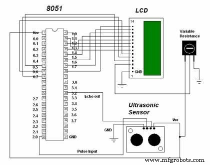
Circuit for Ultrasonic Object Detection
Working Procedure
The 8051 and the ultrasonic module form a tightly coupled system. The sensor emits a 40 kHz burst; when an obstacle is present, the echo returns. The sensor’s echo pin outputs a TTL pulse whose width is proportional to the round‑trip time. The microcontroller measures this pulse width, calculates distance, and drives the LCD and LED accordingly.
With a 12 MHz crystal, the 8051’s 1 µs instruction cycle allows precise timing. The distance is computed as Distance = (Pulse Width × 343 m/s) / 2, where the speed of sound in air is approximately 343 m/s.
Extending the design, the system can log distance data, trigger alarms, or control robotic motion.
Ultrasonic Sensor Details
The sensor requires a 5 V supply and uses a 10 µs TTL trigger pulse. The echo output is a TTL PWM signal whose width equals the echo delay. Typical specifications include:
- Input voltage: 5 V DC
- Static current: <2 mA
- Output voltage: 5 V high / 0 V low
- Detection range: 2 cm to 500 cm
- Dimensions: 34 mm × 20 mm × 15 mm
- Trigger: 10 µs TTL impulse
- Echo: TTL PWM output
Connection Guidelines
- Vcc: +5 V
- GND: Ground (connect before Vcc to avoid damage)
- Trig: Digital pin (e.g., P2.0)
- Echo: Digital pin (e.g., P2.1)
Advantages
- Accurate, contact‑less measurement from 2 cm to 3 m
- Operates in all lighting conditions, ideal as an infrared supplement
- Built‑in LED indicator shows active measurement
- 3‑pin header enables solder‑less connection to development boards
Applications
Typical use cases include:
- Security systems and motion‑sensing camera triggers
- Parking assistance and obstacle avoidance in robotics
- Interactive exhibits and wildlife photography automation
- Burglar alarms and environmental monitoring
About the 8051 Microcontroller
The 8051 is a classic 8‑bit Harvard‑architecture microcontroller, available in a 40‑pin DIP package and powered by a 5 V supply. It contains:
- 4 KB on‑chip ROM/EPROM program memory
- 128 bytes on‑chip RAM
- Eight‑bit data bus, 16‑bit address bus
- Two 16‑bit timers (T0, T1)
- 32 general‑purpose registers (R0–R15, duplicated in banks)
- Five interrupt sources (INT0–INT3, EINT)
- Four 8‑bit parallel ports (P0–P3) totaling 32 I/O lines
- One 16‑bit program counter, stack pointer, and data pointer
- Serial port on P3.0 (RX) and P3.1 (TX), TTL‑level; use MAX232 for RS‑232
- Instruction cycle: 1 µs at 12 MHz crystal
Pin Configuration
Key pins: VCC, GND, XTAL1/XTAL2 (crystal), RST, EA, PSEN. Connect a 12 MHz crystal across XTAL1 and XTAL2 with a 30 pF load capacitor. If a crystal is not used, leave XTAL pins unconnected.
Serial Communication
Serial data is managed by the SCON register on P3.0/P3.1. To interface with PCs or other devices, employ a MAX232 line driver to convert TTL logic to RS‑232 voltage levels.
Project Extensions
Beyond basic detection, the circuit can:
- Calculate exact distances and map obstacle positions
- Act as a motion‑triggered camera system
- Serve as a security alarm with LCD feedback
- Integrate with robot navigation modules
We hope this guide provides a solid foundation for building your own ultrasonic distance sensor with the 8051. For questions or project ideas, feel free to comment below.
Sensor
- Mastering AC Circuit Equations: Impedance, Reactance & Resonance
- Passive Infrared Sensor Power‑Saver Circuit: Design, Operation, and Applications
- Intrusion Detection Systems: Protecting Your Network with Smart Alerts
- Highly Sensitive Nonenzymatic Glucose Sensing with Hollow Porous Nickel Oxide
- Advanced Fall Detection System Using Arduino, Windows IoT, and Azure Cloud
- High-Performance Manganese Oxide Supercapacitor: Merging Battery Storage with Rapid Charging
- High‑Resolution 3D X‑Ray Imaging for Accurate Object Retrieval
- Mastering Ultrasonic Sensor Circuits: The Ultimate Guide
- Build an Ultrasonic Fogger Circuit: Step‑by‑Step Guide
- Precision Ultrasonic Transducer Circuits for Accurate Object Detection