


Isotropic Fiber Fill: Building the Strongest 3D-Printed Parts – Part 2
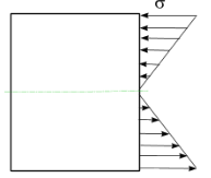
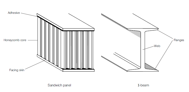
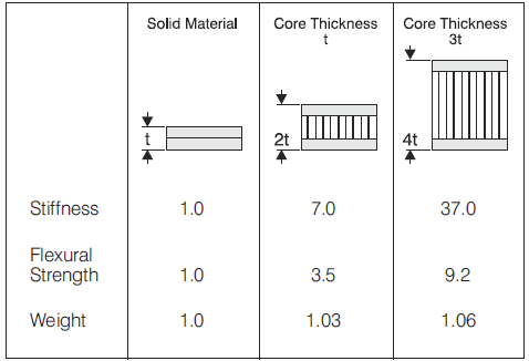
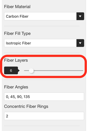
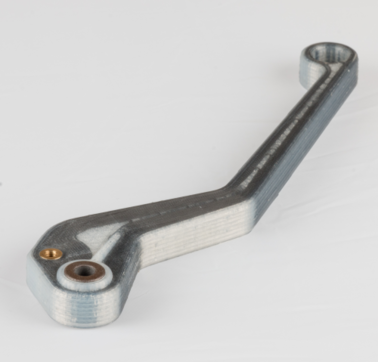
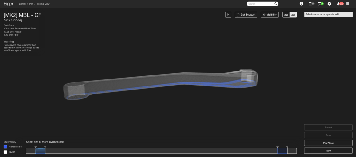
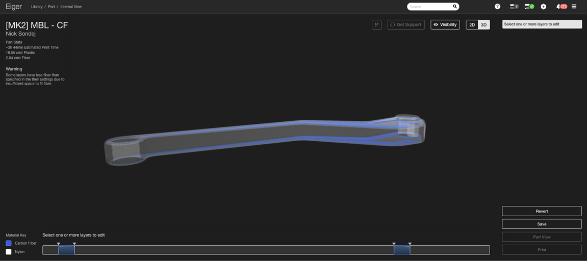
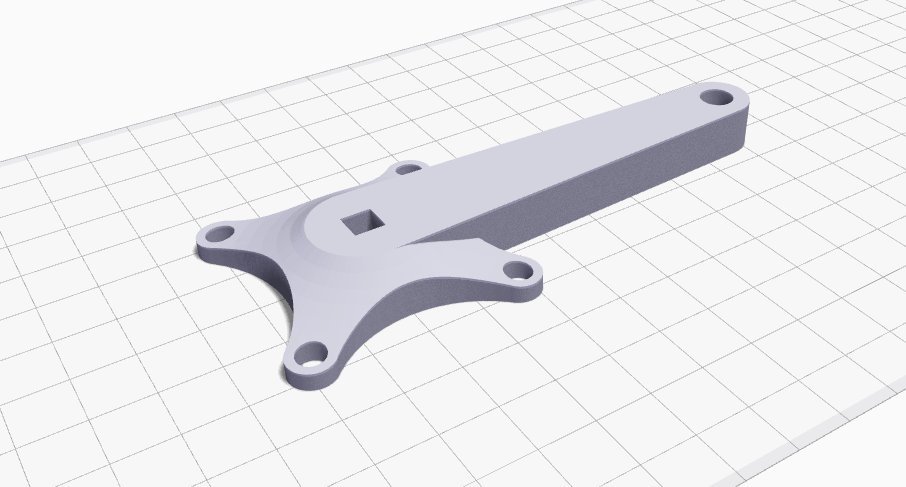
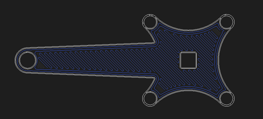
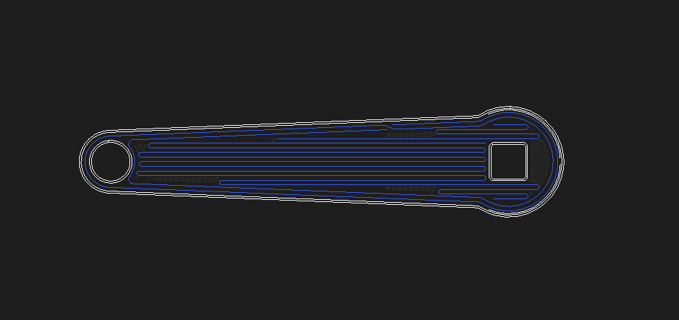
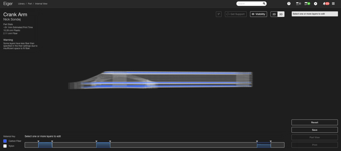
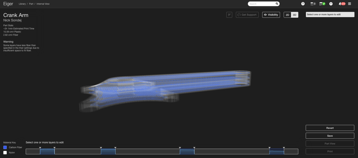
Update: Want to learn how different fills can strengthen your parts and the science behind it? Join our webinar on June 21 at 11 am EDT. Register here Writer’s Note: This is the second post in our two-part series on designing the strongest parts with Eiger’s Isotropic Fiber fill using carbon fiber on the Mark Two. The previous post covered the fundamentals of composite reinforcement and the rationale behind our unique Isotropic pattern. Here we focus on how to apply that fill most efficiently to produce the strongest parts while minimizing weight and cost. We’ve already explored the basics of composite reinforcement and fiber orientations in Eiger. Now we dive into reinforcement efficiency—maximizing strength without adding unnecessary mass or expense. Reinforcing a layer with Eiger’s Isotropic Fiber fill adds stiffness and strength, but is it always needed? The answer lies in the layer’s location relative to the loads that the part will experience. Before reinforcing, it’s essential to understand how physical parts respond to external forces. Consider a simply supported beam that is supported at both ends and free to translate along the x axis, as shown below. When a force F is applied, the beam bends downward. The magnitude of deflection depends on F, the beam’s geometry, and its material properties. A cross‑sectional view of the beam under bending shows that the side closest to the load is compressed, while the opposite side is in tension. The diagram illustrates the bending stresses σ across the beam’s thickness. The arrows’ lengths represent stress magnitude, while their direction indicates compression (upward arrows) or tension (downward arrows). The neutral axis—where stress is zero—runs through the center. This means that the highest stresses occur at the outer surfaces. Therefore, if you’re reinforcing a part that will bend, you should place high‑strength material near those surfaces, mirroring the design principles behind I‑beams and sandwich panels. I‑beams and sandwich panels were developed to achieve high strength and stiffness with minimal weight. Because bending stresses peak at the outer surfaces, adding high‑strength material there maximizes load‑bearing capacity while keeping mass low. Sandwich panels spread the load across a larger area, allowing lighter core materials and reducing the need for a concentrated web. In Eiger, the default algorithm creates a sandwich panel when you add fiber from the Part View page. Half of the selected Fiber Layers are placed on the top of the part (below the top four solid plastic layers) and the other half on the bottom (above the first four solid plastic layers). This works well for parts symmetrical about a plane parallel to the build plate, such as the landing gear for the Snotbot drone printed by Olin College. As shown in the photos, the algorithm added 10 layers of Kevlar reinforcement to the top and bottom of the part, producing a balanced sandwich panel. However, when a part is not symmetrical—like the motorcycle brake lever we often use at trade shows—the default algorithm fails to place fiber where it is most needed. In that case, the algorithm adds fiber only to the bottom, leaving the top surface under‑reinforced because the small ridge from the bronze bushing disrupts symmetry. To create the largest sandwich panel, you must reposition the top layer group so that fiber reaches the lever’s top surface. Our first guideline for strong parts on the Mark Two is to build the largest, thickest sandwich panels first by using Isotropic Fiber fill with one or two concentric rings in layers that are farthest apart. For the brake lever, move the top layer group down until fiber runs at the top of the lever body, as illustrated below. When multiple potential sandwich panel regions overlap—like the crank arm from the UW‑Madison Human Powered Vehicles Team’s 2016 design—you can superimpose panels. The crank arm has several areas that could benefit from reinforcement: the main body’s top and bottom, and the flanged ends that experience bolt‑induced stress cones. Start by letting the default algorithm add four layers of Isotropic Fiber fill to the top and bottom of the entire part. Even though the two layers have different cross‑sectional areas, this approach maximizes the part’s ability to resist the cyclist’s bending loads. Next, reinforce the flange that connects the crank arm to the crank. Since we already reinforced the bottom of the flange in the first step, add a group of layers about 25 layers into the part, right where the flange ends. This creates a second, thinner sandwich panel that shares the bottom skin layer with the larger panel, a concept we call superimposition. Finally, because bicycle crank arms experience complex torsional loads, add an additional fiber layer around the midplane to counter shear stresses, which peak near the neutral axis. This yields a configuration with four distinct fiber groups forming a series of sandwich panels. These steps produce one of the strongest yet lightweight configurations achievable with Eiger. Three key guidelines for high‑strength 3D printing with fiber reinforcement: While exceptions exist, these guidelines provide a solid foundation for designing robust parts. Ready to reinforce a part yourself? Explore the Mark Two today!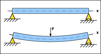
Superimposing Sandwich Panels in Eiger
3D printing
- 3D Printing & Prototyping at Mar‑Bal: Accelerating Composite Innovation
- High‑Speed 3D Printing with the AION500 MK3 – Unmatched Speed, Precision, and Strength
- Metal 3D Printing Applications: Advanced Use Cases – Part 2
- Metal 3D Printing Applications: Prototyping & Tooling – Part 1
- Upgrading the 3DR Iris+ with 3D‑Printed Carbon Fiber Parts – Part 2: Electrical Modifications
- Mastering Isotropic Fiber 3D Printing: Build Ultra‑Strong Parts with the Mark Two
- Markforged Unveils Metal X at CES 2017: Revolutionizing High‑Strength 3D Printing
- Metal 3D Printing Explained: A Three‑Step Process From Design to Finished Part
- 3D Printing Explained: Part 1 – From Raw Materials to Modern Innovations
- PAEK Filaments: High-Performance Materials for 3D Printing