


Mastering Isotropic Fiber 3D Printing: Build Ultra‑Strong Parts with the Mark Two
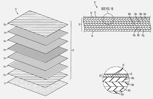
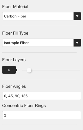
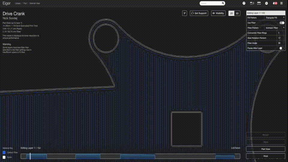
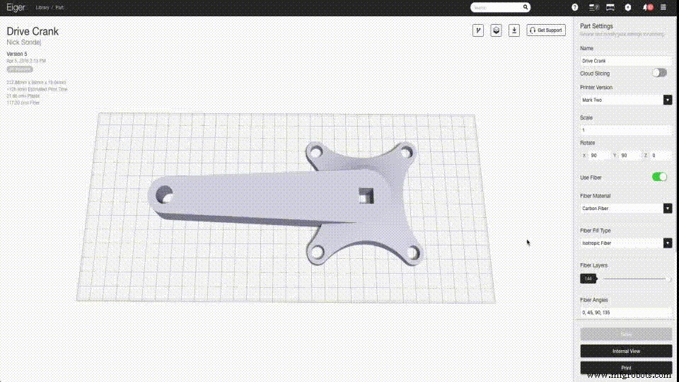
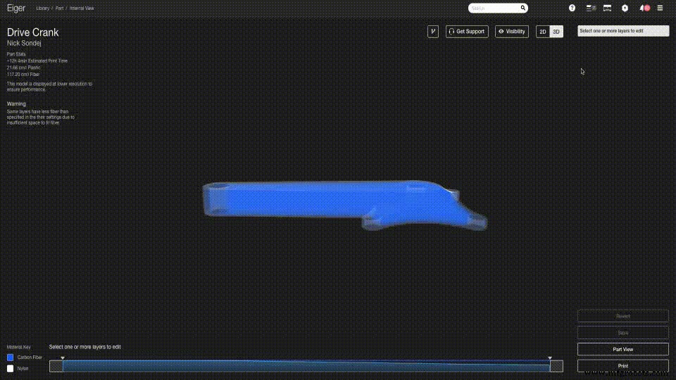
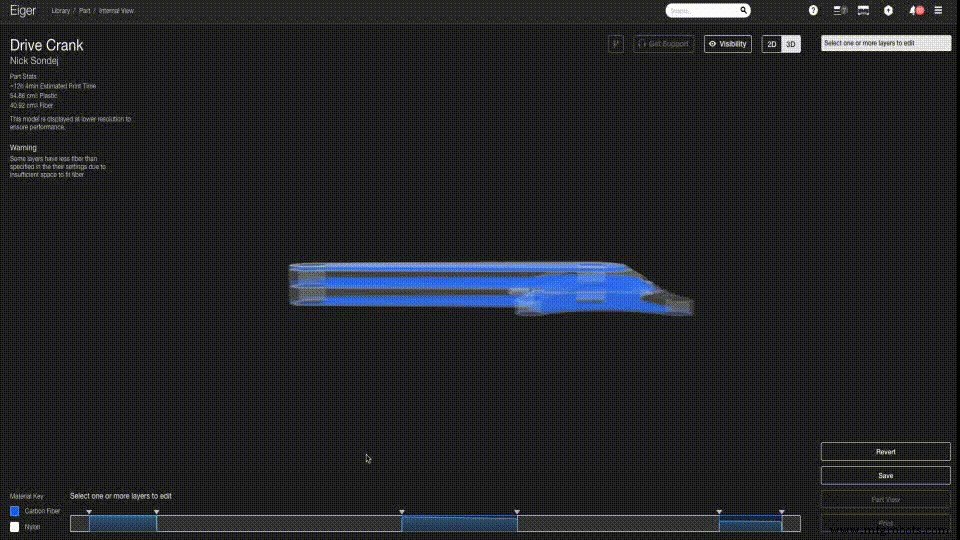
Update: Interested in mastering how different fill patterns enhance part strength and the science behind it? Join our webinar on June 21 at 11 am EDT (Register here). Author’s Note: This is the first of two posts about leveraging Eiger’s Isotropic Fiber fill pattern to create exceptionally strong parts with the Mark Two. In this post, we’ll explore how to emulate the high‑strength lay‑up patterns of traditional composites using a Markforged printer. The follow‑up post will focus on maximizing strength in reinforced parts. We’ll dive into technical details—slowly—using a concise Composites Terminology Glossary to help you design effectively for composite‑reinforced, high‑strength 3D printing. Markforged’s continuous‑strand composite printers enable customers to fabricate industrial‑grade parts reinforced with carbon fibers, producing properties comparable to quasi‑isotropic composite laminates. Quasi‑isotropic 3D‑printed parts exhibit consistent behavior in two axes, with a single direction of variation—ideal for designing parts that resist specific loading conditions. By adjusting fiber orientation in Eiger slicing software, designers can tailor strength to meet target applications. High‑strength isotropic material simplifies engineering design: if a material behaves identically in all directions, geometry alone determines whether it meets strength requirements. When properties vary across axes—as in 3D printing—a quasi‑isotropic material is the next best choice. It requires minimal design effort compared to a fully anisotropic material, as only one axis differs in strength. For clarity, Markforged labels the ‘Isotropic Fiber’ fill type simply as “Isotropic Fiber,” acknowledging that all 3D‑printed parts inherently exhibit different Z‑axis properties. Traditional thermoset composites—most consumer carbon‑fiber applications—use dozens to thousands of unidirectional layers arranged in alternating angles. Composite designers describe these repeat patterns with an “orientation code.” Each successive layer is rotated (often 45°) to produce multi‑directional bulk strength superior to a single‑direction lay‑up. For example, Eiger’s default Isotropic Fiber fill uses the orientation code [0/45/90/135], meaning the first fiber layer aligns horizontally, the second at 45°, and the sequence repeats. Customers can define custom orientation codes of any length, tailoring lay‑up to their design needs. The Mark Two delivers high‑strength fiber‑reinforced parts at up to 15× smaller geometries than the Mark One. Its upgraded software also enhances quasi‑isotropic performance with the Isotropic Fiber fill. In Eiger’s Part View, the Fiber Angles input box reflects the orientation code. Entering a code such as [0/45/90/135] creates a transversely isotropic part when every layer uses Isotropic Fiber. Simply type comma‑separated angles into the box. The new fiber‑routing algorithm lets the Mark Two print Isotropic Fiber with both carbon fiber filament and the new High Strength, High Temperature (HSHT) fiberglass filament—capabilities absent in the Mark One. When you slice a layer with Isotropic Fiber for the Mark Two, the algorithm blends a hybrid fill: concentric rings on the exterior and isotropic fill inside. This yields a superior surface finish while maintaining high internal strength, producing the strongest parts achievable with carbon‑fiber 3D printing. While the External View offers rapid reinforcement, the 3D Internal View provides granular control over layer‑group orientation codes. Start by selecting a part from your Eiger library and opening the Internal View. In the Internal View, click a fiber layer group in the layer bar to edit it. To create a new group, drag from the start or end point across the desired layers, then click Apply Changes to confirm. Resize the group by dragging its triangular delimiters. When a group uses Isotropic Fiber, the Fiber Angles field appears in the upper‑right layer control box. Unlike the global setting in Part View, this allows you to tailor the orientation code for the selected group only, giving you precise control over fiber placement based on part geometry. Eiger’s interface makes it straightforward to configure fiber reinforcement across multiple layers quickly and accurately. Read Part 2 of this series here—we’ll walk through the best strategies for positioning fiber reinforcement to maximize strength and material efficiency. Want to see these capabilities in action? Request a Demo of the Mark Two today!A Composites Background
Composite Terminology Glossary
Improved Capabilities
Fine‑Tuned Reinforcement Control

3D printing
- Achieve Stunning Color Results on Your Next FDM Print
- High‑Strength 3D Printing with Carbon‑Fiber Nylon Composite
- Why Carbon Fiber Luggage Sets Are the Ultimate Upgrade for Travelers
- 3D‑Printed Carbon Fiber: A Superior Alternative to Aluminum Amid Global Shortages
- Upgrading the 3DR Iris+ with 3D‑Printed Carbon Fiber Parts – Part 2: Electrical Modifications
- Quickly Label 3D Printed Parts with Engraver Filler – A Proven, Easy Method
- Optimizing 3D Printed Part Strength with Efficient Fiber Routing – Part 1
- Isotropic Fiber Fill: Building the Strongest 3D-Printed Parts – Part 2
- Markforged Elevates Drone Performance with Carbon‑Fiber 3D Printed Parts – Part 1
- CNC vs. 3D Printing: Choosing the Right Production Method