


Mastering VHDL Port Map Instantiation: A Practical Guide
In VHDL, a module is a self‑contained unit that communicates with the external world through its entity. The port map clause of an instantiation connects the entity’s formal ports to signals in the surrounding design.
Modules, Entities, and Testbenches
When we develop for an FPGA or ASIC, the design logic lives in modules that have clearly defined input and output ports. A module that has no ports is a testbench—a simulation wrapper that feeds stimuli to the device under test (DUT) but never appears on a physical chip.
In earlier posts we wrote all VHDL in a single file, which is convenient for quick experiments but not suitable for production designs. Separating the DUT from its testbench improves readability, reusability, and makes the simulation hierarchy clear.
Common Naming Conventions
Many teams follow a simple scheme: the design file is MyModule.vhd, while its testbench is MyModuleTb.vhd. The architecture of the DUT is often called rtl (register‑transfer level), and the testbench architecture is named sim. This convention instantly tells you whether a file is intended for synthesis or for simulation.

VHDL Syntax for Port Map Instantiation
Define a module’s interface with the entity keyword:
entity <entity_name> is
    port(
        <entity_signal_name> : in|out|inout <signal_type>;
        ...
    );
end entity;
Instantiate the module in another VHDL file with an explicit port map:
<label> : entity <library_name>.<entity_name>(<architecture_name>) port map(
    <entity_signal_name> => <local_signal_name>,
    ...
);
The <label> appears in the simulator hierarchy, <library_name> defaults to work, and every formal port must be bound to a local signal.
Practical Example: 4‑to‑1 MUX
Below is a complete testbench and DUT pair that implements a 4‑to‑1 multiplexer using unsigned 8‑bit signals.
Testbench Code
library ieee;
use ieee.std_logic_1164.all;
use ieee.numeric_std.all;

entity T15_PortMapTb is
end entity;

architecture sim of T15_PortMapTb is

    signal Sig1 : unsigned(7 downto 0) := x"AA";
    signal Sig2 : unsigned(7 downto 0) := x"BB";
    signal Sig3 : unsigned(7 downto 0) := x"CC";
    signal Sig4 : unsigned(7 downto 0) := x"DD";

    signal Sel : unsigned(1 downto 0) := (others => '0');
    signal Output : unsigned(7 downto 0);

begin

    -- Instantiate the MUX with architecture rtl
    i_Mux1 : entity work.T15_Mux(rtl) port map(
        Sel    => Sel,
        Sig1   => Sig1,
        Sig2   => Sig2,
        Sig3   => Sig3,
        Sig4   => Sig4,
        Output => Output);

    -- Stimulus process
    process is
    begin
        wait for 10 ns;
        Sel <= Sel + 1;
        wait for 10 ns;
        Sel <= Sel + 1;
        wait for 10 ns;
        Sel <= Sel + 1;
        wait for 10 ns;
        Sel <= Sel + 1;
        wait for 10 ns;
        Sel <= "UU";
        wait;
    end process;

end architecture;
Module Code
library ieee;
use ieee.std_logic_1164.all;
use ieee.numeric_std.all;

entity T15_Mux is
    port(
        -- Inputs
        Sig1 : in unsigned(7 downto 0);
        Sig2 : in unsigned(7 downto 0);
        Sig3 : in unsigned(7 downto 0);
        Sig4 : in unsigned(7 downto 0);

        Sel  : in unsigned(1 downto 0);

        -- Output
        Output : out unsigned(7 downto 0)
    );
end entity;

architecture rtl of T15_Mux is
begin
    process(Sel, Sig1, Sig2, Sig3, Sig4) is
    begin
        case Sel is
            when "00" => Output <= Sig1;
            when "01" => Output <= Sig2;
            when "10" => Output <= Sig3;
            when "11" => Output <= Sig4;
            when others => Output <= (others => 'X');
        end case;
    end process;
end architecture;
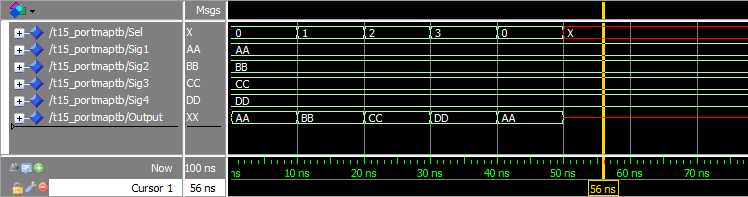
Waveform Analysis
Running the testbench in ModelSim produces a waveform that matches the expected behavior of the MUX. The waveform snapshot below confirms that the DUT correctly switches between the four input signals as the Sel signal changes.
Key Takeaways
- Modules expose inputs and outputs via their
entityports. - Testbenches contain no ports and are solely for simulation.
- Explicit port mapping is the most transparent way to instantiate a VHDL module.
- Consistent naming (e.g.,
rtlfor DUT,simfor testbench) improves readability across projects.
Continue to the next tutorial for deeper insights into VHDL design patterns.
VHDL
- Leveraging In‑Process Procedures for Cleaner VHDL FSM Design
- Using Impure Functions in VHDL: Enhancing FSM Readability and Maintainability
- Mastering VHDL Functions: A Practical Guide to Efficient Design
- Using Procedures in VHDL: Simplify Your Design with Reusable Code
- Leveraging Constants and Generic Maps in VHDL for Flexible Module Design
- Mastering the Case-When Statement in VHDL: Efficient Multiplexer Design
- Mastering Signed and Unsigned Types in VHDL: A Practical Guide
- Mastering VHDL Wait Statements: Wait On, Wait Until, and Combined Usage
- Mastering While Loops in VHDL: Dynamic Iteration Control
- Mastering For‑Loops in VHDL: A Practical Guide