

Industrial manufacturing
CNC Machine
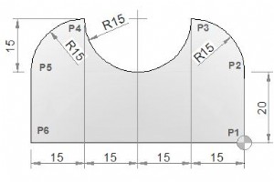
CNC milling machine program which combines/joins multiple arcs.Multiple Arc CNC Mill Program G2 G3 I JCNC Part ProgramN10 M6 T1 G43 H1 M3N15 S500 F120N20 G0 X0 Y0 (P1)N25 G1 Y20 (P2)N30 G3 X-15 Y35 I-15 J0 (P3)N35 G2 X-45 Y35 I-15 J0 (P4)N40 G3 X-60 Y20 I0 J-15 (P5)
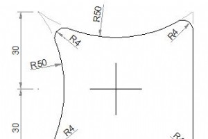
G02 G03 Circular interpolation CNC mill example program.G02 G03 Example CNC MillCNC Part ProgramG0 X30 Y-30 (P1)G1 Y22.67 (P2)G3 X24.07 Y26.18 R4 (P3)G2 X-18.27 Y23.46 R50 (P4)G3 X-23.46 Y18.27 R4 (P5)G2 X-23.46 Y-18.27 R50 (P6)G3 X-18.27 Y-23.46 R4 (P7)G2 X24.0
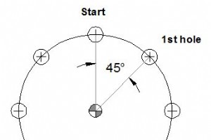
Fadal L93NN Bolt Hole Circle (BHC)Fadal L93NN subroutine is used for pattern drilling in a circle usually called Bolt Hole Circle.ProgrammingN5 L93NN R0... R1... R2...ParametersParameterDescriptionR0Direction and distance in X-axis from starting position to center of circle.R1Direction and distance
A cnc mill program for cnc machinists programmers, who have started to learning basic cnc programming techniques.CNC Mill Example ProgramCNC ProgramN40 G90 G00 X0 Y0N50 G01 X-10 Y-20 R8 (P1)N60 G01 X-50 R10 (P2)N70 Y10 (P3)N80 X-19.97 Y25.01 (P4)N90
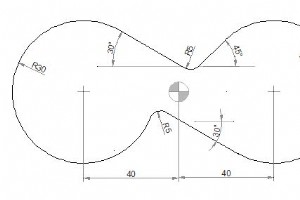
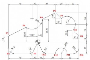
CNC mill program example for cnc machinists.CNC Mill Programming ExampleCNC ProgramG0 X-60 Y0G1 X-70 (P1)G2 X-25.02 Y25.97 R30 (P2)G1 X2.46 Y10.13 (P3)G3 X8.5 Y10.92 R5 (P4)G1 X18.79 Y21.21 (P5)G2 X25.13 Y-26.05 I21.21 J-21.21 (P6)G1 X-5 Y-8.66
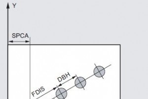
Sinumerik HOLES1 Row of holesSinumerik HOLES1 cycle is used to produce a row of holes on a straight line.ProgrammingG17 Plane activeHOLES1 (SPCA, SPCO, STA1, FDIS, DBH, NUM)ParametersParameterDescriptionSPCAReference point in X-axis (absolute)SPCOReference point in Y-axis (absolute)STA1Starting ang
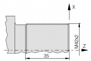
Submit by: Sinumerik Programmer Drawing/Image CNC Program G54G53 G0 X610 Z350T5 D1 G95 S1000 M4G0 X44 Z12CYCLE97(,42,0,-35,42,42,10,3,2.76, ,30, ,5,2,3,1,1)G0 X200 Z100M30
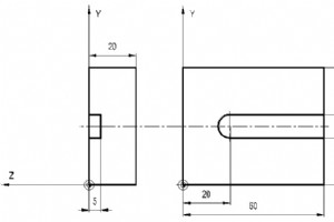
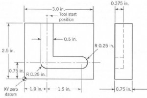
Submit by: Brian Drawing/Image CNC Program 0 BEGIN PGM 1 MM1 BLK FORM 0.1 Z X+0 Y+0 Z-202 BLK FORM 0.2 X+50 Y+56 Z+03 TOOL DEF 1 L+0 R+54 TOOL CALL 1 Z S 22005 L X+57 Y+25 Z+2 R0 FMAX M036 L Z-5 R F80 M7 L X+20 R F M8 L Z+20 R F M9 L X-40 Y+60 R F M0210 END PGM 1
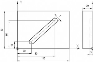
Submit by: Brian Drawing/Image CNC Program 0 BEGIN PGM 1 MM1 BLK FORM 0.1 Z X+0 Y+0 Z-202 BLK FORM 0.2 X+110 Y+80 Z+03 TOOL DEF 1 L+0 R+3.54 TOOL CALL 1 Z S 22005 L X+30 Y+15 Z+2 R0 FMAX M036 L Z-5 R F40 M7 L X+80 Y+60 R F M8 L Z+20 R F M9 L X-40 Y+60 R F M0210 END PGM 1
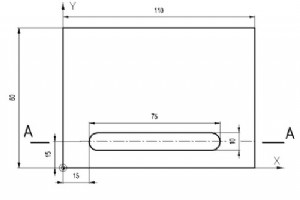
Submit by: Brian Drawing/Image CNC Program 0 BEGIN PGM 1 MM1 BLK FORM 0.1 Z X+0 Y+0 Z-202 BLK FORM 0.2 X+110 Y+80 Z+03 TOOL DEF 1 L+0 R+54 TOOL CALL 1 Z S 22005 L X+20 Y+15 Z+2 R0 FMAX M036 L Z-5 R F40 M7 L X+85 Z-7 R F M8 L Z+20 R F M9 L X-40 Y+60 R F M0210 END PGM 1
Submit by: Brian Drawing/Image CNC Program 0 BEGIN PGM 1 MM1 BLK FORM 0.1 Z X+0 Y+0 Z-202 BLK FORM 0.2 X+50 Y+56 Z+03 TOOL DEF 1 L+0 R+4,54 TOOL CALL 1 Z S 22005 L X+5 Y-7 Z+2 R0 FMAX M036 L Z-5 RL F40 M7 L Y+51 R F80 M8 L X+45 R F M9 L Y+5 R F M10 L X-10 R F M11 L Z+2 R0 FMAX M12 L X+26 Y-7 R0
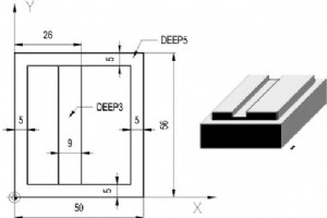
Submit by: Brian Drawing/Image CNC Program 0 BEGIN PGM 1 MM1 BLK FORM 0.1 Z X+0 Y+0 Z-202 BLK FORM 0.2 X+50 Y+56 Z+03 TOOL DEF 1 L+0 R+3,54 TOOL DEF 2 L+0 R+35 TOOL CALL 1 Z S 24006 L X+5 Y-7 Z+2 R0 FMAX M037 L Z-3 RL F40 M8 L Y+51 R F80 M9 L X+45 R F M10 L Y+5 R F M11 L X-10 R F M12 L Z+2 R0 FM
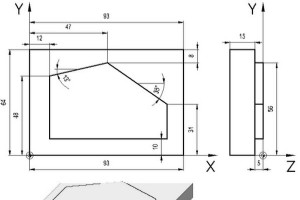
Submit by: Brian Drawing/Image CNC Program 0 BEGIN PGM 1 MM1 BLK FORM 0.1 Z X+0 Y+0 Z-152 BLK FORM 0.2 X+93 Y+64 Z+03 TOOL DEF 1 L+0 R+174 TOOL CALL 1 Z S 24005 L X-20 Y+10 Z+2 R0 FMAX M036 L Z-5 RR F40 M7 L X+83 R F80 M8 L Y+31 R F M9 L X+47 Y+56 R F M10 L X+12 Y+48 R F M11 L Y-20 R F M12 L Z+2
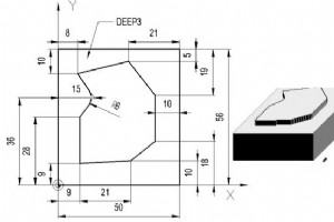
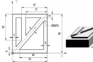
Submit by: Brian Drawing/Image CNC Program 0 BEGIN PGM 1 MM1 BLK FORM 0.1 Z X+0 Y+0 Z-202 BLK FORM 0.2 X+50 Y+56 Z+03 TOOL DEF 1 L+0 R+64 TOOL DEF 2 L+0 R+155 TOOL CALL 1 Z S 24006 L X-20 Y+9 Z+2 R0 FMAX M037 L Z-3 RR F40 M8 L X+30 Y+10 R F80 M9 L X+40 IY+8 R F M10 L Y+37 R F M11 L X+29 Y+51 R F
Submit by: Tanveer Drawing/Image CNC Program O1234 (Program Number)N5 G90 G20 (ABSOLUTE COORDINATE. IN INCHES)N10 M06 T3 (TOOLCHANGE TO TOOL #3)N15 M03 S1250 (SPINDLE ON CW AT 1250RPM)N20 G00 X1 Y1 (RAPID OVER TO X1 Y1)N25 Z0.1 (RAPID DOWN TO Z0.1)N30 G01 Z-0.125 F5 (FEED DOWN TO Z-0.125 AT 5IPM

Submit by: Machinist CNC Program T? M6 (THREADMILL)G0 G90 G40 G21 G17 G94 G80G54 X? Y? S? M3 (Move to bore centre)G43 Z? H?;G65 P1002 A? B? D?(A = THREAD DIAMETER)(B = PITCH)(D = RADIUS OFFSET NUMBER)M30O1002#11=[[#1*0.8]/2]#12=[[#1/2]-#11];G91 Y#12G41 X#11 D#7G3 X-#11 Y#11 R#11 Z#2/4J-[#1/2] Z#2
Submit by: Machinist CNC Program T? M6 (ENDMILL)G0 G90 G40 G21 G17 G94 G80G54 X? Y? S? M3 (Move to bore centre)G43 Z? H?;G65 P1001 A? D?(A = C/BORE DIAMETER)(D = RADIUS OFFSET NUMBER)M30O1001#11=[[#1*0.8]/2]#12=[[#1/2]-#11]G91 Y#12G41 X#11 D#7G3 X-#11 Y#11 R#11J-[#1/2]X-#11 Y-#11 R#11G1 G40 X#11G
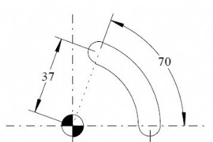
Submit by: Machinist Drawing/Image CNC Program ;A = #1 (Start Angle 0 degrees);B = #2 (Start Radius);C = #3 (Increment angle for accuracy calculations.);I = #4 (Finish Angle);J = #5 (Finish radius);K = #6 (Milling feed)O2222T5 M6G0 G90 G40 G21 G17 G94 G80G54 X35 Y0 S500 M3G43 Z100 H?Z5G1 Z-0.5 F
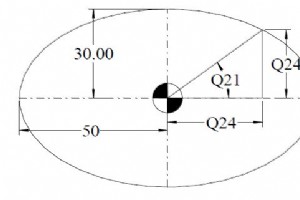
Submit by: Machinist Drawing/Image CNC Program T1 M6G0 G90 G40 G21 G17 G94 G80G54 X0 Y0 S? M3G43 Z5 H?G1 Z-? F?#20 = 2 ; Incremental degree calculation#21 = 0 ; Start Angle#22 = 30 ; Y Axis Radius#23 = 50 ; X Axis RadiusG41 X#23 D? ; Compensation motion to right side of internal pocketN10 #21 =
Submit by: Brian Drawing/Image CNC Program % (Indicates start of program)N005 G90 G70 (Specifies absolute dimensions, inch units)N010 G97 G94 T01 (Specifies units for speed and feed rate; loads first tool)N015 G00 X1000 Y3000 Z250 F0 (Rapid positioning of tool to start point)N020 G01 Z-375 M03 S
CNC Machine

Transformerless Inverters: Key Benefits and How They Revolutionize Solar Power
RONA & OEE: The Key Metrics for Asset Utilization & Profitability
MDF CNC Cutting Projects & Top Machine Recommendations
SmartWay: Comprehensive Kit for Vibrating Motor, RGB LED, GPS Module & Arduino MKR Fox 1200 Projects

