


Building Your First FPGA: LED Blink Tutorial (VHDL & Verilog)
Introduction
Welcome to a hands‑on guide that walks you through creating a simple LED blinker on an FPGA using either VHDL or Verilog. The example demonstrates core FPGA concepts: concurrent processes, frequency synthesis, and multiplexer logic—all driven by a 25 MHz clock.
Project Overview
- Generate four selectable blink frequencies: 100 Hz, 50 Hz, 10 Hz, and 1 Hz.
- Maintain a 50 % duty cycle for each frequency.
- Enable the LED only when an
LED_ENswitch is asserted. - Choose the desired frequency via two independent switches.
- Simulation is required before deploying to hardware to catch errors early.
Frequency Selection Truth Table
| Enable | Switch 1 | Switch 2 | LED Drive Frequency |
|---|---|---|---|
| 0 | - | - | (disabled) |
| 1 | 0 | 0 | 100 Hz |
| 1 | 0 | 1 | 50 Hz |
| 1 | 1 | 0 | 10 Hz |
| 1 | 1 | 1 | 1 Hz |
Signal Definitions
| Signal Name | Direction | Description |
|---|---|---|
| i_clock | Input | 25 MHz system clock |
| i_enable | Input | LED enable switch (logic 0 = off) |
| i_switch_1 | Input | Frequency selector bit 1 |
| i_switch_2 | Input | Frequency selector bit 0 |
| o_led_drive | Output | Drive signal for the LED |
Design Philosophy
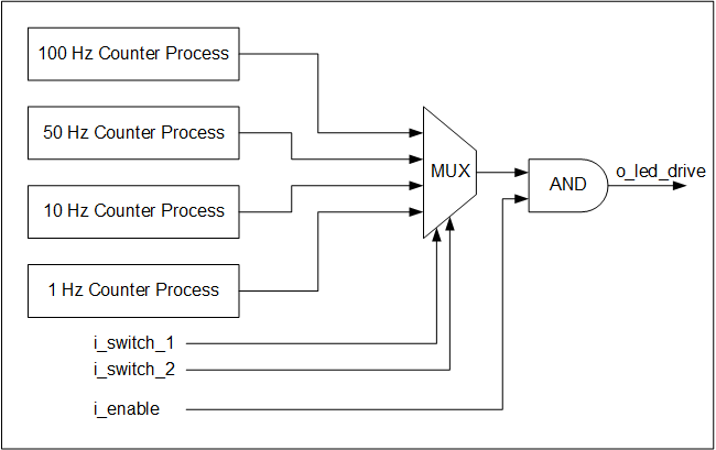
Four independent counter processes run concurrently, each toggling a local signal at its target frequency. Even when a particular frequency is not selected, its counter continues to run—this is the hallmark of FPGA concurrency.
The switches implement a combinational multiplexer that routes the desired toggle signal to the LED driver. The LED_EN switch acts as an active‑high gate, ensuring the LED turns off when the enable is low.
Block Diagram
VHDL Implementation
Below is a fully commented VHDL module that satisfies the specification. The counter constants are calculated using the formula:
count = (clock frequency / target frequency) × 0.5 to achieve a 50 % duty cycle.
library ieee;
use ieee.std_logic_1164.all;
use ieee.numeric_std.all;

entity tutorial_led_blink is
  port (
    i_clock      : in  std_logic;
    i_enable     : in  std_logic;
    i_switch_1   : in  std_logic;
    i_switch_2   : in  std_logic;
    o_led_drive  : out std_logic
  );
end tutorial_led_blink;

architecture rtl of tutorial_led_blink is

  -- Frequency constants (half‑period counts)
  constant c_CNT_100HZ : natural := 125000;   -- 25 MHz / 100 Hz × 0.5
  constant c_CNT_50HZ  : natural := 250000;   -- 25 MHz / 50 Hz  × 0.5
  constant c_CNT_10HZ  : natural := 1250000;  -- 25 MHz / 10 Hz  × 0.5
  constant c_CNT_1HZ   : natural := 12500000; -- 25 MHz / 1 Hz   × 0.5

  -- Counter signals
  signal r_CNT_100HZ : natural range 0 to c_CNT_100HZ;
  signal r_CNT_50HZ  : natural range 0 to c_CNT_50HZ;
  signal r_CNT_10HZ  : natural range 0 to c_CNT_10HZ;
  signal r_CNT_1HZ   : natural range 0 to c_CNT_1HZ;

  -- Toggle outputs
  signal r_TOGGLE_100HZ : std_logic := '0';
  signal r_TOGGLE_50HZ  : std_logic := '0';
  signal r_TOGGLE_10HZ  : std_logic := '0';
  signal r_TOGGLE_1HZ   : std_logic := '0';

  -- Multiplexer selection
  signal w_LED_SELECT : std_logic;

begin

  -- 100 Hz toggling process
  p_100_HZ : process (i_clock) is
  begin
    if rising_edge(i_clock) then
      if r_CNT_100HZ = c_CNT_100HZ-1 then
        r_TOGGLE_100HZ <= not r_TOGGLE_100HZ;
        r_CNT_100HZ    <= 0;
      else
        r_CNT_100HZ <= r_CNT_100HZ + 1;
      end if;
    end if;
  end process p_100_HZ;

  -- 50 Hz toggling process
  p_50_HZ : process (i_clock) is
  begin
    if rising_edge(i_clock) then
      if r_CNT_50HZ = c_CNT_50HZ-1 then
        r_TOGGLE_50HZ <= not r_TOGGLE_50HZ;
        r_CNT_50HZ    <= 0;
      else
        r_CNT_50HZ <= r_CNT_50HZ + 1;
      end if;
    end if;
  end process p_50_HZ;

  -- 10 Hz toggling process
  p_10_HZ : process (i_clock) is
  begin
    if rising_edge(i_clock) then
      if r_CNT_10HZ = c_CNT_10HZ-1 then
        r_TOGGLE_10HZ <= not r_TOGGLE_10HZ;
        r_CNT_10HZ    <= 0;
      else
        r_CNT_10HZ <= r_CNT_10HZ + 1;
      end if;
    end if;
  end process p_10_HZ;

  -- 1 Hz toggling process
  p_1_HZ : process (i_clock) is
  begin
    if rising_edge(i_clock) then
      if r_CNT_1HZ = c_CNT_1HZ-1 then
        r_TOGGLE_1HZ <= not r_TOGGLE_1HZ;
        r_CNT_1HZ    <= 0;
      else
        r_CNT_1HZ <= r_CNT_1HZ + 1;
      end if;
    end if;
  end process p_1_HZ;

  -- Multiplexer based on switch inputs
  w_LED_SELECT <= r_TOGGLE_100HZ when (i_switch_1 = '0' and i_switch_2 = '0') else
                  r_TOGGLE_50HZ  when (i_switch_1 = '0' and i_switch_2 = '1') else
                  r_TOGGLE_10HZ  when (i_switch_1 = '1' and i_switch_2 = '0') else
                  r_TOGGLE_1HZ;

  -- Gate the LED drive with the enable switch
  o_led_drive <= w_LED_SELECT and i_enable;

end rtl;
Verilog Implementation
Below is an equivalent Verilog module. The design philosophy is identical—four independent always blocks, each toggling at a specific frequency, and a combinational multiplexer driven by the switches.
module tutorial_led_blink
  (
   i_clock,
   i_enable,
   i_switch_1,
   i_switch_2,
   o_led_drive
   );

  input i_clock;
  input i_enable;
  input i_switch_1;
  input i_switch_2;
  output o_led_drive;

  // Frequency parameters (half‑period counts)
  parameter c_CNT_100HZ = 125000;
  parameter c_CNT_50HZ  = 250000;
  parameter c_CNT_10HZ  = 1250000;
  parameter c_CNT_1HZ   = 12500000;

  // Counter registers
  reg [31:0] r_CNT_100HZ = 0;
  reg [31:0] r_CNT_50HZ  = 0;
  reg [31:0] r_CNT_10HZ  = 0;
  reg [31:0] r_CNT_1HZ   = 0;

  // Toggle registers
  reg r_TOGGLE_100HZ = 1'b0;
  reg r_TOGGLE_50HZ  = 1'b0;
  reg r_TOGGLE_10HZ  = 1'b0;
  reg r_TOGGLE_1HZ   = 1'b0;

  // Multiplexer selection
  reg r_LED_SELECT;
  wire w_LED_SELECT;

  // 100 Hz toggle block
  always @(posedge i_clock) begin
    if (r_CNT_100HZ == c_CNT_100HZ-1) begin
      r_TOGGLE_100HZ <= ~r_TOGGLE_100HZ;
      r_CNT_100HZ    <= 0;
    end else
      r_CNT_100HZ <= r_CNT_100HZ + 1;
  end

  // 50 Hz toggle block
  always @(posedge i_clock) begin
    if (r_CNT_50HZ == c_CNT_50HZ-1) begin
      r_TOGGLE_50HZ <= ~r_TOGGLE_50HZ;
      r_CNT_50HZ    <= 0;
    end else
      r_CNT_50HZ <= r_CNT_50HZ + 1;
  end

  // 10 Hz toggle block
  always @(posedge i_clock) begin
    if (r_CNT_10HZ == c_CNT_10HZ-1) begin
      r_TOGGLE_10HZ <= ~r_TOGGLE_10HZ;
      r_CNT_10HZ    <= 0;
    end else
      r_CNT_10HZ <= r_CNT_10HZ + 1;
  end

  // 1 Hz toggle block
  always @(posedge i_clock) begin
    if (r_CNT_1HZ == c_CNT_1HZ-1) begin
      r_TOGGLE_1HZ <= ~r_TOGGLE_1HZ;
      r_CNT_1HZ    <= 0;
    end else
      r_CNT_1HZ <= r_CNT_1HZ + 1;
  end

  // Combinational multiplexer
  always @(*) begin
    case ({i_switch_1, i_switch_2})
      2'b11: r_LED_SELECT <= r_TOGGLE_1HZ;
      2'b10: r_LED_SELECT <= r_TOGGLE_10HZ;
      2'b01: r_LED_SELECT <= r_TOGGLE_50HZ;
      2'b00: r_LED_SELECT <= r_TOGGLE_100HZ;
    endcase
  end

  // Drive LED with enable gating
  assign o_led_drive = r_LED_SELECT & i_enable;

endmodule
Simulation & Verification
Prior to programming the FPGA, run a behavioral simulation (e.g., with ModelSim, VCS, or Vivado Simulator). Verify that each toggle signal matches the expected period and that the multiplexer correctly routes the signal based on the switch combination. Simulating early eliminates costly hardware debugging and confirms that the 50 % duty cycle is maintained.
Conclusion
This tutorial demonstrates how to build a compact, reusable LED blinker that can be adapted to other timing tasks. The same counter‑based frequency synthesis pattern scales to more complex state machines, making it a foundational skill for any FPGA developer.
VHDL
- C# Hello World – Building Your First C# Application
- Your First VHDL Program: A Step‑by‑Step Hello World Tutorial
- C Hello World: Your First Program – A Step‑by‑Step Guide
- Java Hello World: Step‑by‑Step Guide to Writing Your First Java Program
- Hello World: Building Your First Python Application
- Master Verilog: Complete Tutorial for Digital Circuit Design
- Fast-Track Your Custom Quote: Accurate Pricing in 2–3 Days
- Designing an Effective Preventative Maintenance Program for Equipment
- Master PADS PCB Design: Advanced Features & Tutorials
- First CNC Program: Step-by-Step CNC Machining Guide