



How to Build Your First FPGA LED Blinker: A Step‑by‑Step Tutorial
Step‑by‑Step Guide: Building Your First FPGA LED Blinker
Part 1: Designing VHDL or Verilog
In this tutorial you’ll learn how to craft VHDL and Verilog code that drives an LED at a user‑defined frequency. Choose the language that best fits your workflow.
When writing HDL, you must verify that the design behaves as intended. Mistakes are inevitable, so simulation is indispensable. This tutorial is split into two critical phases:
- HDL Design
- HDL Simulation
Skipping simulation can lead to costly on‑hardware debugging. Treat simulation as a mandatory checkpoint.
Project Requirements
Write HDL that blinks an LED at 100 Hz, 50 Hz, 10 Hz, or 1 Hz with a 50 % duty cycle. Two switches select the desired frequency, and an additional LED_EN switch must be high to enable the LED. The FPGA runs on a 25 MHz oscillator.
Truth table for the frequency selector:
| Enable | Switch 1 | Switch 2 | LED Drive Frequency |
|---|---|---|---|
| 0 | – | – | disabled |
| 1 | 0 | 0 | 100 Hz |
| 1 | 0 | 1 | 50 Hz |
| 1 | 1 | 0 | 10 Hz |
| 1 | 1 | 1 | 1 Hz |
Signal summary:
| Signal Name | Direction | Description |
|---|---|---|
| i_clock | Input | 25 MHz clock |
| i_enable | Input | Enable switch (logic 0 = LED off) |
| i_switch_1 | Input | Frequency selector switch 1 |
| i_switch_2 | Input | Frequency selector switch 2 |
| o_led_drive | Output | LED drive signal |
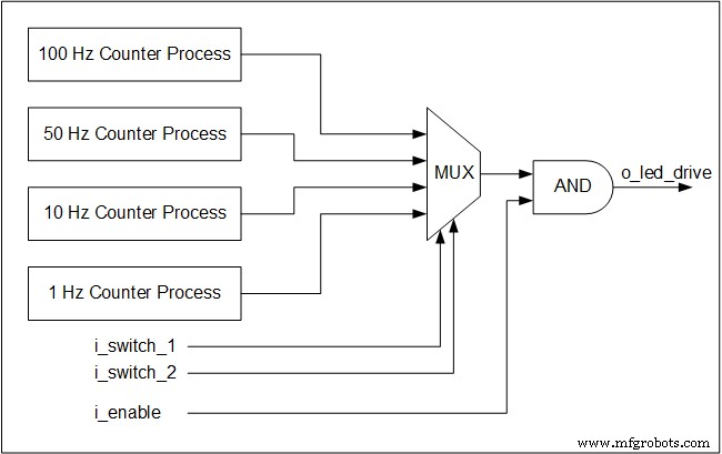
Four concurrent counter processes monitor the 25 MHz clock and generate toggles for each target frequency. Even when a particular frequency isn’t selected, its counter continues to run – a core principle of hardware concurrency.
The switches form a multiplexer that routes the chosen toggle to the LED output. Multiplexers are purely combinational logic, so they operate without a clock.
Below is a block diagram illustrating the architecture:
VHDL Implementation
library ieee;
use ieee.std_logic_1164.all;
use ieee.numeric_std.all;
entity tutorial_led_blink is
 port (
 i_clock : in std_logic;
 i_enable : in std_logic;
 i_switch_1 : in std_logic;
 i_switch_2 : in std_logic;
 o_led_drive : out std_logic
 );
end tutorial_led_blink;
architecture rtl of tutorial_led_blink is
 -- Constants to create the frequencies needed:
 -- Formula is: (25 MHz / 100 Hz * 50% duty cycle)
 -- So for 100 Hz: 25,000,000 / 100 * 0.5 = 125,000
 constant c_CNT_100HZ : natural := 125000;
 constant c_CNT_50HZ : natural := 250000;
 constant c_CNT_10HZ : natural := 1250000;
 constant c_CNT_1HZ : natural := 12500000;
 -- These signals will be the counters:
 signal r_CNT_100HZ : natural range 0 to c_CNT_100HZ;
 signal r_CNT_50HZ : natural range 0 to c_CNT_50HZ;
 signal r_CNT_10HZ : natural range 0 to c_CNT_10HZ;
 signal r_CNT_1HZ : natural range 0 to c_CNT_1HZ;

 -- These signals will toggle at the frequencies needed:
 signal r_TOGGLE_100HZ : std_logic := '0';
 signal r_TOGGLE_50HZ : std_logic := '0';
 signal r_TOGGLE_10HZ : std_logic := '0';
 signal r_TOGGLE_1HZ : std_logic := '0';
 -- One bit select wire.
 signal w_LED_SELECT : std_logic;

begin
 -- All processes toggle a specific signal at a different frequency.
 -- They all run continuously even if the switches are
 -- not selecting their particular output.

 p_100_HZ : process (i_clock) is
 begin
 if rising_edge(i_clock) then
 if r_CNT_100HZ = c_CNT_100HZ-1 then -- -1, since counter starts at 0
 r_TOGGLE_100HZ <= not r_TOGGLE_100HZ;
 r_CNT_100HZ <= 0;
 else
 r_CNT_100HZ <= r_CNT_100HZ + 1;
 end if;
 end if;
 end process p_100_HZ;
 p_50_HZ : process (i_clock) is
 begin
 if rising_edge(i_clock) then
 if r_CNT_50HZ = c_CNT_50HZ-1 then -- -1, since counter starts at 0
 r_TOGGLE_50HZ <= not r_TOGGLE_50HZ;
 r_CNT_50HZ <= 0;
 else
 r_CNT_50HZ <= r_CNT_50HZ + 1;
 end if;
 end if;
 end process p_50_HZ;

 p_10_HZ : process (i_clock) is
 begin
 if rising_edge(i_clock) then
 if r_CNT_10HZ = c_CNT_10HZ-1 then -- -1, since counter starts at 0
 r_TOGGLE_10HZ <= not r_TOGGLE_10HZ;
 r_CNT_10HZ <= 0;
 else
 r_CNT_10HZ <= r_CNT_10HZ + 1;
 end if;
 end if;
 end process p_10_HZ;

 p_1_HZ : process (i_clock) is
 begin
 if rising_edge(i_clock) then
 if r_CNT_1HZ = c_CNT_1HZ-1 then -- -1, since counter starts at 0
 r_TOGGLE_1HZ <= not r_TOGGLE_1HZ;
 r_CNT_1HZ <= 0;
 else
 r_CNT_1HZ <= r_CNT_1HZ + 1;
 end if;
 end if;
 end process p_1_HZ;

 -- Create a multiplexor based on switch inputs
 w_LED_SELECT <= r_TOGGLE_100HZ when (i_switch_1 = '0' and i_switch_2 = '0') else
 r_TOGGLE_50HZ when (i_switch_1 = '0' and i_switch_2 = '1') else
 r_TOGGLE_10HZ when (i_switch_1 = '1' and i_switch_2 = '0') else
 r_TOGGLE_1HZ;

 -- Only allow o_led_drive to drive when i_enable is high (and gate).
 o_led_drive <= w_LED_SELECT and i_enable;
end rtl;
Verilog Implementation
module tutorial_led_blink
(
 i_clock,
 i_enable,
 i_switch_1,
 i_switch_2,
 o_led_drive
 );
 input i_clock;
 input i_enable;
 input i_switch_1;
 input i_switch_2;
 output o_led_drive;

 // Constants (parameters) to create the frequencies needed:
 // Input clock is 25 kHz, chosen arbitrarily.
 // Formula is: (25 kHz / 100 Hz * 50% duty cycle)
 // So for 100 Hz: 25,000 / 100 * 0.5 = 125
 parameter c_CNT_100HZ = 125;
 parameter c_CNT_50HZ = 250;
 parameter c_CNT_10HZ = 1250;
 parameter c_CNT_1HZ = 12500;
 // These signals will be the counters:
 reg [31:0] r_CNT_100HZ = 0;
 reg [31:0] r_CNT_50HZ = 0;
 reg [31:0] r_CNT_10HZ = 0;
 reg [31:0] r_CNT_1HZ = 0;

 // These signals will toggle at the frequencies needed:
 reg r_TOGGLE_100HZ = 1'b0;
 reg r_TOGGLE_50HZ = 1'b0;
 reg r_TOGGLE_10HZ = 1'b0;
 reg r_TOGGLE_1HZ = 1'b0;

 // One bit select
 reg r_LED_SELECT;
 wire w_LED_SELECT;


begin
 // All always blocks toggle a specific signal at a different frequency.
 // They all run continuously even if the switches are
 // not selecting their particular output.
 always @ (posedge i_clock)
 begin
 if (r_CNT_100HZ == c_CNT_100HZ-1) // -1, since counter starts at 0
 begin
 r_TOGGLE_100HZ <= !r_TOGGLE_100HZ;
 r_CNT_100HZ <= 0;
 end
 else
 r_CNT_100HZ <= r_CNT_100HZ + 1;
 end

 always @ (posedge i_clock)
 begin
 if (r_CNT_50HZ == c_CNT_50HZ-1) // -1, since counter starts at 0
 begin
 r_TOGGLE_50HZ <= !r_TOGGLE_50HZ;
 r_CNT_50HZ <= 0;
 end
 else
 r_CNT_50HZ <= r_CNT_50HZ + 1;
 end
 always @ (posedge i_clock)
 begin
 if (r_CNT_10HZ == c_CNT_10HZ-1) // -1, since counter starts at 0
 begin
 r_TOGGLE_10HZ <= !r_TOGGLE_10HZ;
 r_CNT_10HZ <= 0;
 end
 else
 r_CNT_10HZ <= r_CNT_10HZ + 1;
 end

 always @ (posedge i_clock)
 begin
 if (r_CNT_1HZ == c_CNT_1HZ-1) // -1, since counter starts at 0
 begin
 r_TOGGLE_1HZ <= !r_TOGGLE_1HZ;
 r_CNT_1HZ <= 0;
 end
 else
 r_CNT_1HZ <= r_CNT_1HZ + 1;
 end
 // Create a multiplexer based on switch inputs
 always @ (*)
 begin
 case () // Concatenation Operator
 2'b11 : r_LED_SELECT <= r_TOGGLE_1HZ;
 2'b10 : r_LED_SELECT <= r_TOGGLE_10HZ;
 2'b01 : r_LED_SELECT <= r_TOGGLE_50HZ;
 2'b00 : r_LED_SELECT <= r_TOGGLE_100HZ;
 endcase
 end
 assign o_led_drive = r_LED_SELECT & i_enable;
 // Alternative way to design multiplexer (same as above):
 // More compact, but harder to read, especially to those new to Verilog
 // assign w_LED_SELECT = i_switch_1 ? (i_switch_2 ? r_TOGGLE_1HZ : r_TOGGLE_10HZ) :
 //(i_switch_2 ? r_TOGGLE_50HZ : r_TOGGLE_100HZ);
 // assign o_led_drive = w_LED_SELECT & i_enable;


end

endmodule
Next Step: Simulate this design in VHDL or Verilog to confirm correct behavior before deployment.
VHDL
- Creating a Tcl-Driven Testbench for a VHDL Code‑Lock Module
- Using Procedures in VHDL: Simplify Your Design with Reusable Code
- Driving VHDL Testbenches from External Stimulus Files with TEXTIO
- Building Your First FPGA: LED Blink Tutorial (VHDL & Verilog)
- Enhance Hardware Verification with a Tcl-Based Interactive Testbench
- VHDL Variables Explained: Practical Examples & Rules for Reliable Design
- VUnit 101: A Practical Guide to Automated VHDL Verification
- Leveraging VHDL Records for Clean, Reusable FIFO Interfaces
- Mastering For‑Loops in VHDL: A Practical Guide
- Build a Reliable Timer in VHDL: Counting Clock Cycles to Hours