


Mastering VHDL’s std_logic: States, Resolution, and Waveform Analysis
In VHDL, the std_logic type is the cornerstone for representing a single bit on a physical wire. Unlike the plain integer type used in earlier tutorials, std_logic offers a richer set of values that model real‑world digital signal behavior more accurately.
While a digital pin usually carries either a logic high ('1') or a logic low ('0'), a physical signal can also appear in high‑impedance, weak, or undefined states. The std_logic type captures all of these possibilities, making it the most frequently employed type in VHDL design.
This article is part of the Basic VHDL Tutorials series.
Below is the full list of values that a std_logic signal can assume:
| '1' | Logic 1 |
| '0' | Logic 0 |
| 'Z' | High impedance |
| 'W' | Weak signal; indeterminate 0 or 1 |
| 'L' | Weak 0 (pulldown) |
| 'H' | Weak 1 (pullup) |
| '-' | Don’t care |
| 'U' | Uninitialized |
| 'X' | Unknown (multiple drivers) |
In most tutorials we’ll focus on the primary values '1' and '0', and occasionally 'U' and 'X' to highlight design errors. The remaining states are advanced features useful for modeling protocols like I2C or creating tri‑state buses.
When several processes drive the same std_logic signal, the language employs a resolution function to determine the resulting value. This mechanism prevents compile‑time or run‑time errors in simulations and is defined by a resolution table, as shown below.
| U | X | 0 | 1 | Z | W | L | H | - | |
|---|---|---|---|---|---|---|---|---|---|
| U | X | X | 1 | 1 | 1 | 1 | 1 | X | 1 |
| U | X | 0 | X | 0 | 0 | 0 | 0 | X | 0 |
| U | U | U | U | U | U | U | U | U | U |
| U | X | X | X | X | X | X | X | X | X |
| U | X | 0 | 1 | Z | W | L | H | X | Z |
| U | X | 0 | 1 | W | W | W | W | X | W |
| U | X | 0 | 1 | L | W | L | W | X | L |
| U | X | 0 | 1 | H | W | W | H | X | H |
| U | X | X | X | X | X | X | X | X | - |
Exercise
This video tutorial demonstrates how to declare std_logic signals and visualize them in a waveform simulation.
The final VHDL code produced in this exercise is shown below:
library ieee;
use ieee.std_logic_1164.all;

entity T10_StdLogicTb is
end entity;

architecture sim of T10_StdLogicTb is

    signal Signal1 : std_logic := '0';
    signal Signal2 : std_logic;
    signal Signal3 : std_logic;

begin

    process is
    begin

        wait for 10 ns;
        Signal1 <= not Signal1;

    end process;

    -- Driver A
    process is
    begin

        Signal2 <= 'Z';
        Signal3 <= '0';
        wait;

    end process;

    -- Driver B
    process(Signal1) is
    begin

        if Signal1 = '0' then
            Signal2 <= 'Z';
            Signal3 <= 'Z';
        else
            Signal2 <= '1';
            Signal3 <= '1';
        end if;

    end process;

end architecture;
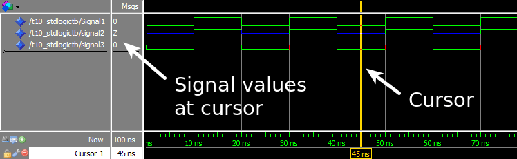
The waveform window in ModelSim after pressing run and zooming into the timeline:
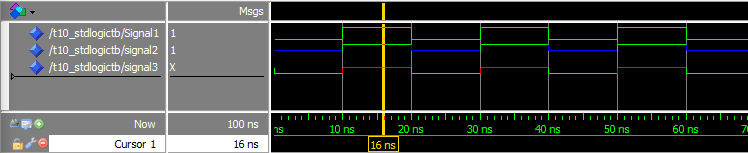
The waveform with the cursor placed on the other part of the repeating signal cycle:
Analysis
This exercise illustrates the VHDL resolution function in action. By inspecting the waveform rather than relying solely on textual output, we gain a clearer view of how multiple drivers interact on a std_logic signal.
Signal1 is toggled by a single process, so its value alternates cleanly between '0' and '1'. Signals driven by both Driver A and Driver B resolve according to the table displayed earlier.
| Signal | Driver A | Driver B | Result |
|---|---|---|---|
| Signal2 | 'Z' | 'Z' | 'Z' |
| Signal2 | 'Z' | '1' | '1' |
| Signal3 | '0' | 'Z' | '0' |
| Signal3 | '0' | '1' | 'X' |
Takeaway
std_logicis the most widely used VHDL type for single‑bit signals.- Think of a
std_logicsignal as a physical wire carrying a digital value. - When multiple processes drive the same
std_logicsignal, the resolution function determines the final value.
Go to the next tutorial »
VHDL
- Leveraging In‑Process Procedures for Cleaner VHDL FSM Design
- Using Impure Functions in VHDL: Enhancing FSM Readability and Maintainability
- Mastering VHDL Functions: A Practical Guide to Efficient Design
- Using Procedures in VHDL: Simplify Your Design with Reusable Code
- Mastering the Case-When Statement in VHDL: Efficient Multiplexer Design
- Mastering Signed and Unsigned Types in VHDL: A Practical Guide
- Mastering VHDL Wait Statements: Wait On, Wait Until, and Combined Usage
- Mastering While Loops in VHDL: Dynamic Iteration Control
- Mastering For‑Loops in VHDL: A Practical Guide
- Mastering Loop and Exit Constructs in VHDL: A Practical Guide