


Mastering Signed vs. Unsigned Types in VHDL: Practical Insights
Digital designers rely on precise arithmetic inside FPGAs and ASICs. A core concept is the distinction between signed and unsigned data types in VHDL.
Both types are defined in the numeric_std package from the IEEE library. While many designers still use std_logic_arith, this package is not IEEE‑standard and is not recommended for production designs.
In VHDL, a signed signal is interpreted as a two’s‑complement number, allowing both positive and negative values. An unsigned signal represents only non‑negative values. Internally, the FPGA always uses two’s‑complement for all bit‑vectors, regardless of the type you declare.
| Bits | Unsigned Value | Signed Value |
|---|---|---|
| 011 | 3 | 3 |
| 010 | 2 | 2 |
| 001 | 1 | 1 |
| 000 | 0 | 0 |
| 111 | 7 | -1 |
| 110 | 6 | -2 |
| 101 | 5 | -3 |
| 100 | 4 | -4 |
At first glance this mapping can seem counterintuitive, but once you understand two’s‑complement, the behavior is predictable.
It’s important to note that the binary result of an arithmetic operation is identical whether the operands are declared signed or unsigned. What changes is the interpretation of that result.
For example, adding two 5‑bit vectors:
- Signed: 10001 + 00010 = 10011 (interpreted as –13)
- Unsigned: 10001 + 00010 = 10011 (interpreted as 19)
library ieee;
use ieee.std_logic_1164.all;
use ieee.numeric_std.all;

entity signed_unsigned is
  port (
    i_rst_l : in std_logic;
    i_clk   : in std_logic;
    i_a     : in std_logic_vector(4 downto 0);
    i_b     : in std_logic_vector(4 downto 0)
  );
end signed_unsigned;

architecture behave of signed_unsigned is
  signal rs_SUM_RESULT : signed(4 downto 0)   := (others => '0');
  signal ru_SUM_RESULT : unsigned(4 downto 0) := (others => '0');
  signal rs_SUB_RESULT : signed(4 downto 0)   := (others => '0');
  signal ru_SUB_RESULT : unsigned(4 downto 0) := (others => '0');

begin
  p_SUM : process (i_clk, i_rst_l) begin
    if i_rst_l = '0' then
      rs_SUM_RESULT <= (others => '0');
      ru_SUM_RESULT <= (others => '0');
    elsif rising_edge(i_clk) then
      ru_SUM_RESULT <= unsigned(i_a) + unsigned(i_b);
      rs_SUM_RESULT <= signed(i_a) + signed(i_b);
    end if;
  end process p_SUM;

  p_SUB : process (i_clk, i_rst_l) begin
    if i_rst_l = '0' then
      rs_SUB_RESULT <= (others => '0');
      ru_SUB_RESULT <= (others => '0');
    elsif rising_edge(i_clk) then
      ru_SUB_RESULT <= unsigned(i_a) - unsigned(i_b);
      rs_SUB_RESULT <= signed(i_a) - signed(i_b);
    end if;
  end process p_SUB;

end behave;
Testbench
library ieee;
use ieee.std_logic_1164.all;

entity example_signed_unsigned_tb is
end example_signed_unsigned_tb;

architecture behave of example_signed_unsigned_tb is
  signal r_CLK   : std_logic                    := '0';
  signal r_RST_L : std_logic                    := '0';
  signal r_A     : natural                      := 0;
  signal r_B     : natural                      := 0;
  signal r_A_SLV : std_logic_vector(4 downto 0) := (others => '0');
  signal r_B_SLV : std_logic_vector(4 downto 0) := (others => '0');
  constant c_CLK_PERIOD : time := 10 ns;

  component example_signed_unsigned is
    port (
      i_rst_l : in  std_logic;
      i_clk   : in  std_logic;
      i_a     : in  std_logic_vector(4 downto 0);
      i_b     : in  std_logic_vector(4 downto 0)
    );
  end component example_signed_unsigned;

begin
  i_DUT: example_signed_unsigned
    port map (
      i_rst_l => r_RST_L,
      i_clk   => r_CLK,
      i_a     => r_A_SLV,
      i_b     => r_B_SLV
    );

  clk_gen : process is
  begin
    r_CLK <= '0' after c_CLK_PERIOD/2, '1' after c_CLK_PERIOD;
    wait for c_CLK_PERIOD;
  end process clk_gen;

  process
  begin
    r_RST_L <= '0';
    wait for 20 ns;
    r_RST_L <= '1';
    wait for 20 ns;

    r_A_SLV <= "01001";
    r_B_SLV <= "00110";
    wait for 20 ns;

    r_A_SLV <= "10001";
    r_B_SLV <= "00110";
    wait for 20 ns;

    r_A_SLV <= "10001";
    r_B_SLV <= "00001";
    wait for 20 ns;

    r_A_SLV <= "10001";
    r_B_SLV <= "00010";
    wait for 20 ns;

    r_A_SLV <= "11111";
    r_B_SLV <= "00001";
    wait for 20 ns;

    r_A_SLV <= "00000";
    r_B_SLV <= "00001";
    wait for 20 ns;
    wait;
  end process;

end behave;
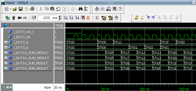
Modelsim simulation wave – Hex values
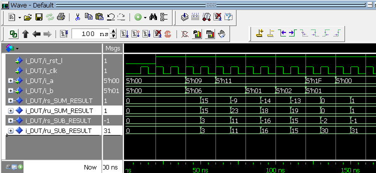
Modelsim simulation wave – Decimal values
The two screenshots demonstrate that the underlying binary results are identical regardless of type. The difference arises only when the simulator displays the values: in hex the same bit pattern appears, while in decimal signed results may appear negative. Careful type handling is essential when designing FPGA logic.
If any part of this topic remains unclear, please email us via the sidebar contact link. We’re happy to help you master signed and unsigned arithmetic.
| Most Popular Nandland Pages |
|---|
VHDL
- Introduction to VHDL: Building Your First AND Gate
- Leveraging VHDL Records for Clean, Reusable FIFO Interfaces
- VHDL Variables Explained: Practical Examples & Rules for Reliable Design
- Mastering VHDL Functions: A Practical Guide to Efficient Design
- Using Procedures in VHDL: Simplify Your Design with Reusable Code
- Build a Reliable Timer in VHDL: Counting Clock Cycles to Hours
- Mastering Signed and Unsigned Types in VHDL: A Practical Guide
- Mastering std_logic_vector: Creating Signal Vectors in VHDL
- Understanding the Difference Between Signals and Variables in VHDL
- What Is VHDL? A Practical Guide to Hardware Description Language