


Introduction to VHDL: Building Your First AND Gate
VHDL, short for Very High Speed Integrated Circuit Hardware Description Language, is one of the two primary hardware description languages used to design FPGAs and ASICs. While it may appear verbose compared to software languages, its syntax is precise and designed for describing digital logic at a very high level of abstraction.
Before diving into VHDL code, it’s helpful to understand the context in which it is used. FPGAs (Field‑Programmable Gate Arrays) and ASICs (Application‑Specific Integrated Circuits) are the building blocks of modern digital systems, from consumer electronics to aerospace applications. VHDL and its counterpart Verilog provide a textual means to describe the behavior and structure of these circuits.
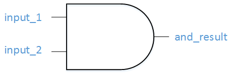
In this tutorial we’ll walk through the creation of a simple AND gate in VHDL. An AND gate accepts two binary inputs and produces a single output that is high only when both inputs are high.
Defining Signals and Operations
The core concept in VHDL is the signal, which represents a wire or a storage element that can hold a value. A signal can be declared with the std_logic type, which is the most common type for binary signals. Here’s a minimal example of how to declare an AND gate operation:
signal and_gate : std_logic;
and_gate <= input_1 and input_2;
The first line declares a signal named and_gate. The second line assigns to that signal the logical AND of input_1 and input_2. The <= operator is the VHDL signal assignment operator, and the keyword and is a reserved operator for logical conjunction.
Creating an Entity
All VHDL files expose a top‑level entity that defines the external interface of the design. For the AND gate, the entity lists two input ports and one output port:
entity example_and is
  port (
    input_1    : in  std_logic;
    input_2    : in  std_logic;
    and_result : out std_logic
  );
end example_and;
Each port specifies its direction (in or out) and its type (std_logic).
Defining the Architecture
The architecture contains the internal behavior of the entity. It can declare additional internal signals and the combinational logic that drives the outputs. A typical architecture for our AND gate looks like this:
architecture rtl of example_and is
  signal and_gate : std_logic;
begin
  and_gate   <= input_1 and input_2;
  and_result <= and_gate;
end rtl;
Within the architecture, all internal signals are declared between the is and begin keywords. The executable statements that drive the signals appear between begin and end.
Including Standard Libraries
At the top of every VHDL file you must reference the IEEE standard library that defines the std_logic type:
library ieee;
use ieee.std_logic_1164.all;
These two lines bring the necessary types and operators into scope for the rest of the file.
Complete Example
Below is the full VHDL source for a two‑input AND gate. Copy this into your VHDL editor and simulate or synthesize it to confirm its behavior.
library ieee;
use ieee.std_logic_1164.all;

entity example_and is
  port (
    input_1    : in  std_logic;
    input_2    : in  std_logic;
    and_result : out std_logic
  );
end example_and;

architecture rtl of example_and is
  signal and_gate : std_logic;
begin
  and_gate   <= input_1 and input_2;
  and_result <= and_gate;
end rtl;
Although the code may seem verbose compared to conventional programming languages, this level of explicitness is essential for reliable hardware synthesis and simulation. As you gain experience, you’ll discover shortcuts and abstractions that reduce repetition while maintaining clarity.
With this foundation, you’re ready to explore more complex circuits, learn about concurrent statements, and integrate VHDL designs into larger FPGA or ASIC projects.
VHDL
- Leveraging VHDL Records for Clean, Reusable FIFO Interfaces
- VHDL Variables Explained: Practical Examples & Rules for Reliable Design
- Verilog Basics: Designing Your First AND Gate
- Foundations and Advancements of AC Motor Technology
- Leveraging In‑Process Procedures for Cleaner VHDL FSM Design
- Mastering VHDL’s std_logic: States, Resolution, and Waveform Analysis
- What Is VHDL? A Practical Guide to Hardware Description Language
- Master C Programming: Comprehensive Tutorial for Beginners
- Straton Runtime: Integrating PLCNext Engineer with IEC61850 for Seamless Data Exchange
- Master SINUMERIK 808D: Beginner Video Tutorial – Turning Part 1