


Understanding Attenuators: Design, Types, and Decibel Calculations
Attenuators are passive components that reduce the amplitude of a signal. They are essential in RF systems, test equipment, and audio chains to protect sensitive receivers or to match power levels.
What Is an Attenuator?
An attenuator weakens a high‑level signal so that a downstream device receives a lower, controlled level. It can be built into a signal generator or added as a standalone module. Common configurations include fixed and adjustable units. In addition to attenuation, a properly matched attenuator provides isolation between the source and the load.
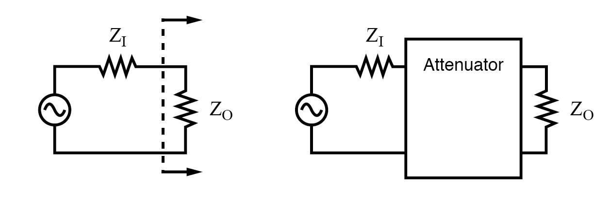
For radio‑frequency equipment the characteristic impedance is typically 50 Ω. A constant‑impedance attenuator matches both the source impedance ZI and the load impedance ZO to preserve signal integrity.
Common Attenuator Networks
Three network topologies are most frequently used:
- T‑section – two series resistors and one shunt resistor.
- Π‑section – two shunt resistors and one series resistor.
- L‑section – a single series resistor followed by a shunt resistor (or vice versa).
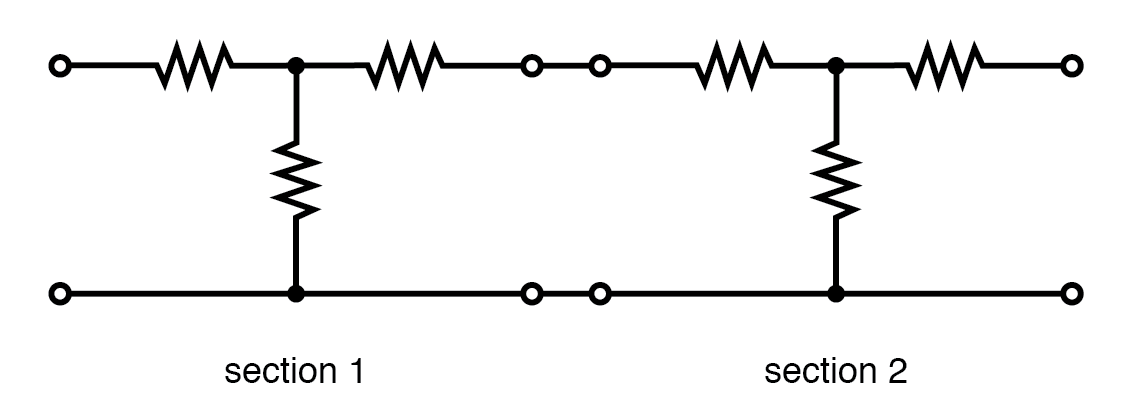
Multiple sections can be cascaded to achieve higher attenuation. The total loss is simply the sum of the individual dB values.

Using Decibels for Attenuation
Decibels (dB) express the ratio of input to output power. For a single attenuator:
dB = 10 log10(PI / PO)
Because power ratios add, cascading a 10 dB and a 6 dB attenuator yields 16 dB of total loss.
10 dB + 6 dB = 16 dB
When the source and load impedances are equal, the dB value can also be derived from the voltage ratio:
dB = 20 log10(VI / VO)
Example Calculations
- 10 W in → 1 W out: dB = 10 log10(10/1) = 10 dB.
- 10 dB attenuator voltage ratio: K = 1010/20 ≈ 3.16.
- 100 mW in → 1 mW out: dB = 10 log10(100/1) = 20 dB.
- 20 dB attenuator voltage ratio: K = 1020/20 = 10.
T‑Section Attenuator
For a 50 Ω system the resistor values for a given attenuation can be calculated from the voltage ratio K:
R1 = Z · (K²–1) / (K²+1)
R2 = Z · (K²–1)
The following table lists values for common dB levels (10 dB, 20 dB, etc.). Multiply the resistances by 600/50 or 75/50 to match 600 Ω or 75 Ω systems.
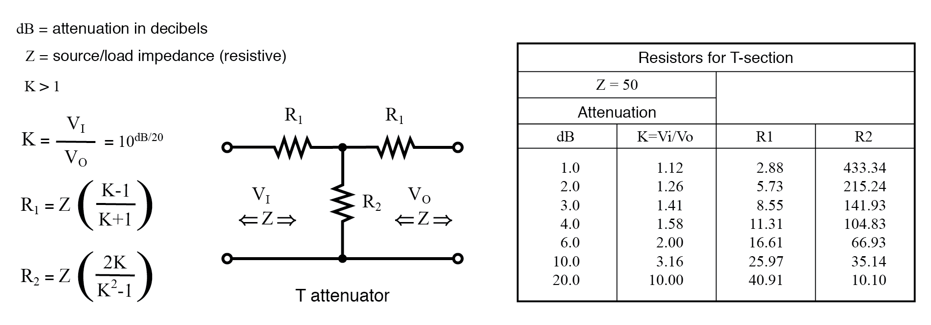
Because the T‑section is symmetric, it can be used in either direction while preserving the 50 Ω match.
Π‑Section Attenuator
Resistor values for a 50 Ω match are derived from:
R1 = R2 = Z · (K–1) / (K+1)
R3 = Z · (K²–1) / (K+1)
The table below provides ready‑made values for standard attenuation levels.

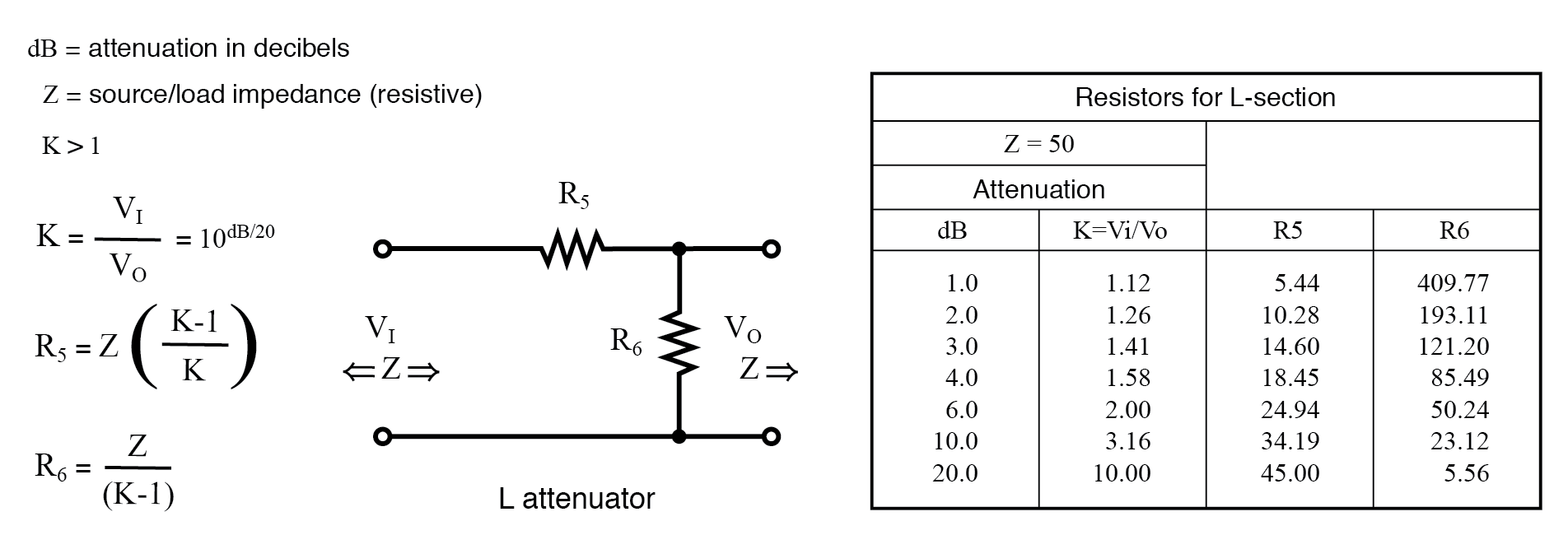
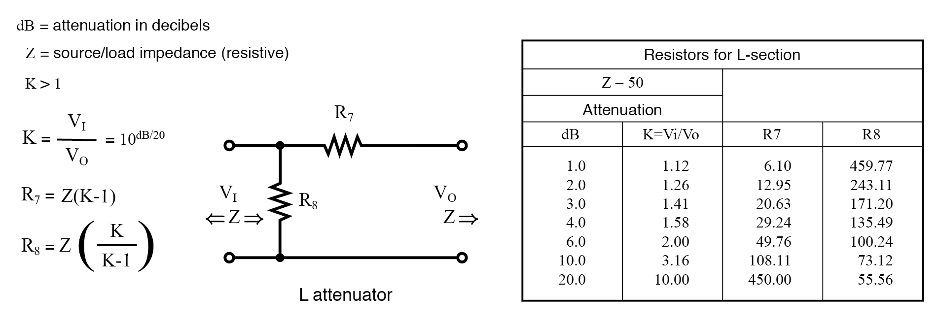
L‑Section Attenuator
Two forms exist: series‑then‑shunt and shunt‑then‑series. The resistor values for a 50 Ω match are given in the accompanying tables.
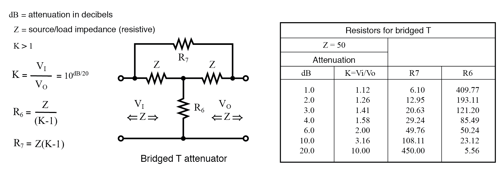
Bridged‑T Attenuator
Bridged‑T networks provide higher attenuation with fewer components but are less common because they require precise matching. Resistor values for a 50 Ω system are shown below.
Cascading and Variable Attenuators
Sections can be cascaded to reach higher total loss. For example, two 10 dB sections give 20 dB. The voltage attenuation ratio multiplies: 3.16 × 3.16 ≈ 10.
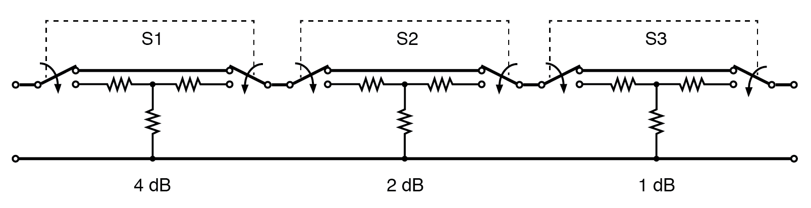
Switchable attenuators provide discrete attenuation steps. A typical 0–7 dB unit uses binary switching of sections.
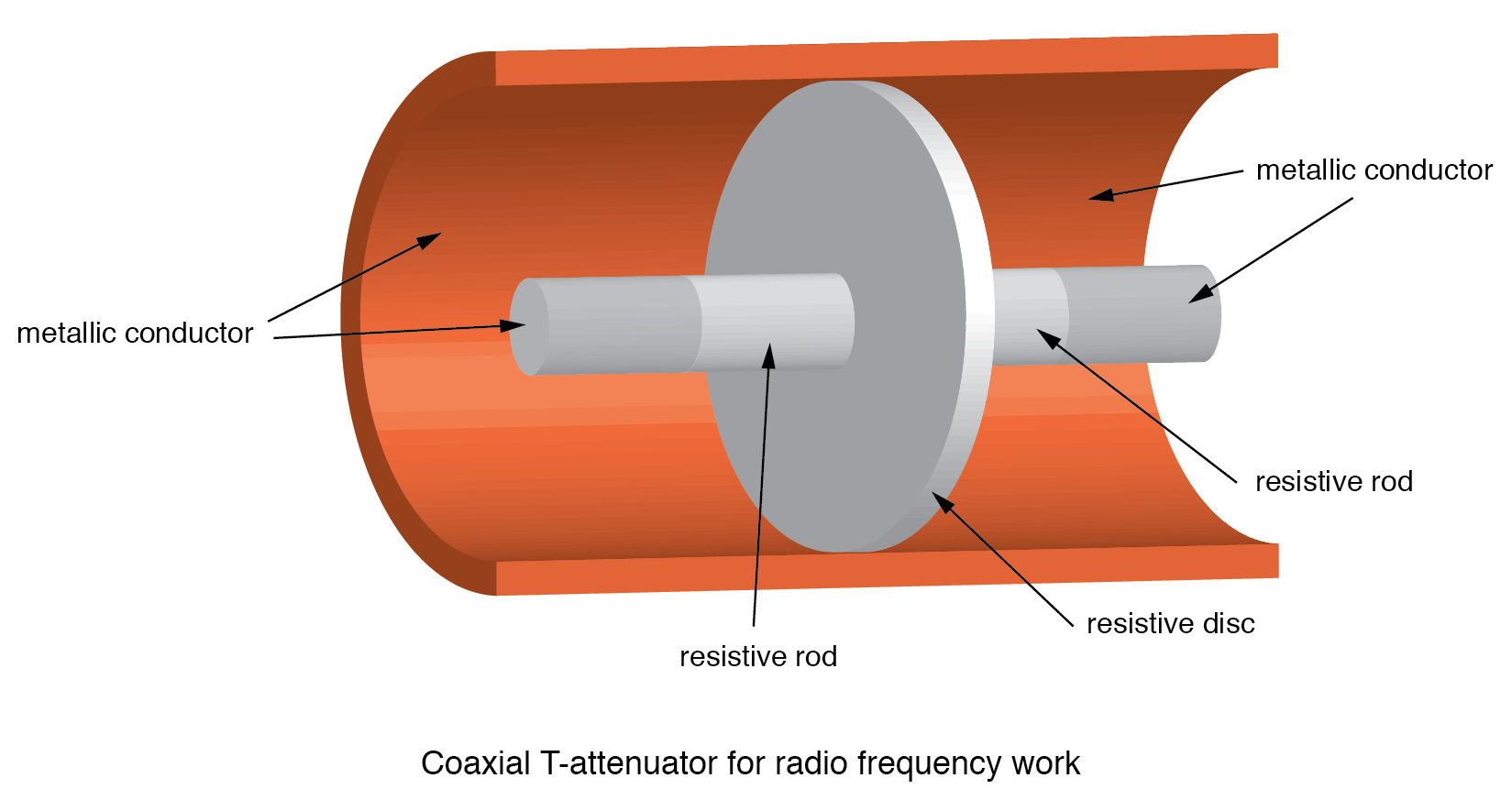
RF‑Specific Attenuators
For frequencies below 1 GHz, individual sections should be shielded to prevent capacitive coupling. At higher frequencies, lead‑less resistive elements or coaxial T and Π designs are used.

Summary
- An attenuator reduces signal amplitude.
- Attenuation is expressed in decibels; dB values add when sections are cascaded.
- dB from power:
dB = 10 log10(PI/PO). - dB from voltage (for matched impedances):
dB = 20 log10(VI/VO). - T and Π sections are the most common configurations for RF applications.
For more detailed calculations, refer to our Decibel Measurements Worksheet.
Industrial Technology
- Electronics: A Hands‑On Science for All
- Setting Up a Home Electronics Lab: Tools, Work Area, and Supplies
- Mastering Voltmeter Use: Accurate Voltage Measurement Made Simple
- Mastering Ohmmeter Measurements: A Practical Guide to Resistance Testing
- Building and Troubleshooting a Basic 6‑V Battery‑Lamp Circuit
- Measuring Current with an Ammeter: A Practical Guide
- Practical Ohm’s Law Experiment: Measuring Voltage, Current, and Resistance
- Exploring Nonlinear Resistance in Incandescent Lamps: A Practical Lab Guide
- Understanding Attenuators: Design, Types, and Decibel Calculations
- Silicon Labs Unveils 5G‑Ready Si539x Jitter Attenuators with Fully Integrated Reference