


Understanding BJT Active‑Mode Operation: From Cut‑Off to Saturation
When a bipolar junction transistor (BJT) is completely off, it is said to be in the cut‑off state, behaving like an open switch. When it conducts to the maximum extent permitted by the supply and load—so that the collector current (IC) is as high as the circuit allows—it is said to be in the saturated state. These two extremes have traditionally been the focus when using a transistor as a simple on/off switch.
However, BJTs are not limited to only these two modes. By supplying a base current that is greater than zero but less than the value that would push the device into saturation, the transistor will operate in an intermediate region known as the active mode. In this regime the base current “opens a gate” that allows a proportional amount of collector current to flow, but the transistor does not fully saturate.
Cut‑Off, Saturation, and Active Mode
Think of the transistor like a car’s powertrain: cut‑off is akin to the brake being fully engaged; active mode is cruising at a steady speed controlled by the driver; and saturation is similar to the accelerator being pushed hard, but the engine cannot deliver more power than the supply allows.
Below is a SPICE model that illustrates active‑mode behavior. The circuit uses an NPN transistor powered by a voltage source (V1) and driven by a current source (I1).
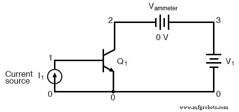
bipolar transistor simulation

i1 0 1 dc 20u
q1 2 1 0 mod1
vammeter 3 2 dc 0
v1 3 0 dc
.model mod1 npn
.dc v1 0 2 0.05
.plot dc i (vammeter)
.end
Circuit diagram and netlist for an active‑mode SPICE simulation.
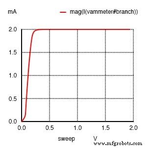
In this model, the base current is fixed at 20 µA while the collector‑emitter voltage (VCE) is swept from 0 V to 2 V. The result is a flat collector‑current curve at 2 mA, demonstrating that the transistor regulates IC to a value determined by the base current rather than by VCE.
Extending the voltage sweep to 50 V confirms that IC remains constant at 2 mA, underscoring the transistor’s role as a current regulator.
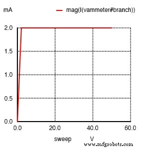
bipolar transistor simulation

i1 0 1 dc 20u
q1 2 1 0 mod1
vammeter 3 2 dc 0
v1 3 0 dc
.model mod1 npn
.dc v1 0 50 2
.plot dc i (vammeter)
.end
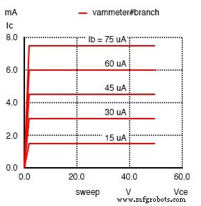
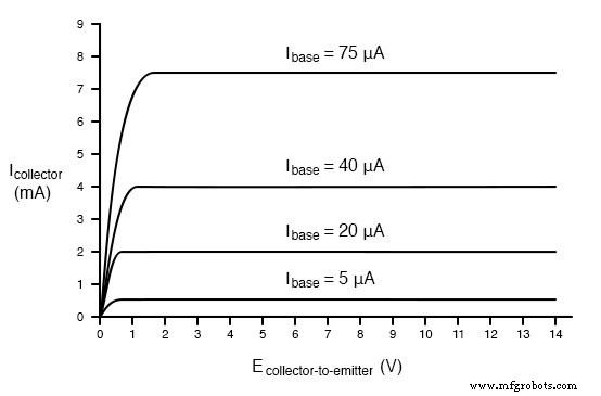
Increasing the base current to 75 µA while sweeping VCE from 0 V to 50 V yields a flat 7.5 mA collector current, again confirming that IC tracks the base current (β = 100). The voltage has virtually no influence beyond the minimum required to maintain the transistor in active mode.
bipolar transistor simulation

i1 0 1 dc 75u
q1 2 1 0 mod1
vammeter 3 2 dc 0
v1 3 0 dc
.model mod1 npn
.dc v1 0 50 2 i1 15u 75u 15u
.plot dc i (vammeter)
.end
These results illustrate a fundamental difference from resistive behavior: a resistor’s current increases linearly with voltage, whereas a BJT limits IC to a fixed maximum regardless of how high VCE rises (once the transistor is driven into its active region).
Superimposing multiple curves for different base currents on a single plot provides the transistor’s characteristic curves. Each curve shows how IC varies with VCE for a particular base‑current value.
The key parameter that links IC and the base current (IB) is the current gain, commonly denoted by the Greek letter β (beta) or, in hybrid‑parameter notation, hfe. The relationship is expressed as:

β is a dimensionless figure of merit that reflects the transistor’s internal design. While it is often quoted as a single value (e.g., 100), in practice β can vary by more than a factor of three across different operating points, temperatures, and frequencies. Consequently, circuit designers typically avoid relying on a fixed β for critical calculations.
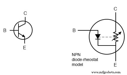
Two popular models help visualize transistor behavior. The first treats the BJT as a diode in series with a variable resistor; this illustrates the idea that base current controls the collector‑emitter resistance. However, it misrepresents the fact that the transistor actually limits current rather than voltage.
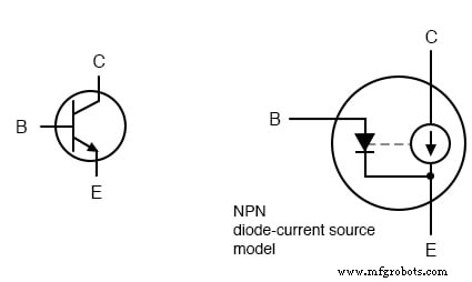
The second, more accurate model represents the transistor as a diode in parallel with a current source whose output is β × IB. This captures the transistor’s true current‑regulating behavior and is widely used in circuit analysis.
Key Takeaways
- In active mode, a BJT operates between full cut‑off and full saturation.
- The base current sets an upper limit on the collector current.
- The ratio IC/IB is the current gain (β or hfe).
- β varies between individual devices and across operating conditions.
- Designs should not depend on a fixed β value; instead, use safety margins or matched transistor sets when necessary.
Related Worksheets
Industrial Technology
- Hands‑On Guide to Current Dividers: Build, Measure, and Simulate with a 6 V Battery
- Bipolar Junction Transistors (BJT): Core Principles and Practical Applications
- BJT Switching: How Transistors Efficiently Control High‑Current Loads
- Understanding BJT Active‑Mode Operation: From Cut‑Off to Saturation
- Common-Emitter Amplifier Limitations: Distortion, Temperature, and High‑Frequency Challenges
- Understanding JFET Active‑Mode Operation: From SPICE Simulations to Transconductance
- Understanding Active-Mode Operation in IGFETs: Design, Performance, and Applications
- Insulated‑Gate Bipolar Transistors (IGBTs): Merging FET Precision with BJT Power
- Understanding Mutual Inductance and Transformer Fundamentals
- DIACs Explained: Design, Functionality, and Key Applications