


Pulse Sensor: How It Works and Key Applications for Makers
Monitoring heart rate is essential for athletes, researchers, and hobbyists, yet calculating it manually can be error‑prone. The Pulse Sensor—a plug‑and‑play optical sensor—provides a quick, reliable way to capture heartbeat data. Designed primarily for Arduino, it’s ideal for students, developers, and artists who want to embed live heart‑rate metrics into projects.
What Is the Pulse Sensor?
Also called a heartbeat or heart‑rate sensor, the Pulse Sensor uses a simple optical method to detect blood flow. Attach it to the fingertip or earlobe, connect it to an Arduino, and the sensor translates pulse peaks into digital signals.
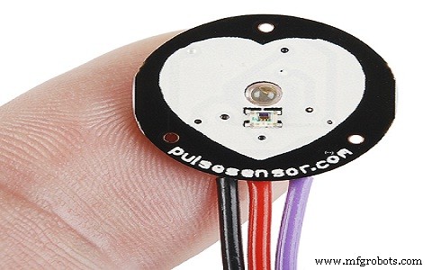
Each sensor bundle includes a 24‑inch color‑coded cable, an ear clip, two Velcro dots, and three transparent stickers—components that simplify wiring and secure the sensor on the body.
- The color‑coded cable connects to header pins, eliminating soldering.
- The ear clip is affixed with hot glue and sits on the earlobe.
- Velcro dots help create a snug strap for fingertip use.
- Transparent stickers protect the sensor from sweat and provide mounting holes.
Pulse Sensor Specifications
The key specs are:
- Biometric pulse‑rate detection
- Diameter: 0.625 in; Thickness: 0.125 in
- Operating voltage: +5 V (±10 % tolerance) or +3.3 V
- Plug‑and‑play design
- Current draw: 4 mA
- Built‑in amplification and noise cancellation
- Not FDA‑approved—suitable for educational and hobby projects, not medical use
Pin Configuration
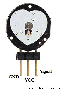
- Pin 1 (GND): Black wire – connects to system ground.
- Pin 2 (VCC): Red wire – supplies +5 V or +3.3 V.
- Pin 3 (Signal): Purple wire – outputs the pulse waveform.
Pulse Sensor Circuit Diagram
For a detailed circuit and application examples, see the Pulse Sensor Circuit with its Applications guide.
How Does the Pulse Sensor Work?
The sensor’s operation is based on photoplethysmography. An infrared LED shines onto the skin, and a photodiode on the opposite side detects the reflected light. As blood volume changes with each heartbeat, the reflected light intensity fluctuates. These micro‑variations are amplified and filtered to produce a clean pulse signal.
Because the LED sits directly above a vein, even minimal blood flow changes generate detectable differences. The sensor’s integrated amplifier boosts the tiny signal, while a noise‑cancellation circuit suppresses ambient light and motion artifacts.
Using the Pulse Sensor with Arduino
Proper installation is critical for accurate readings:
- Secure the sensor with hot glue or a vinyl strip to prevent electrical contact.
- Avoid using the sensor with wet hands—dry contact yields better signal quality.
- Position the sensor so the smooth, optical side faces the vein, typically the fingertip or earlobe.
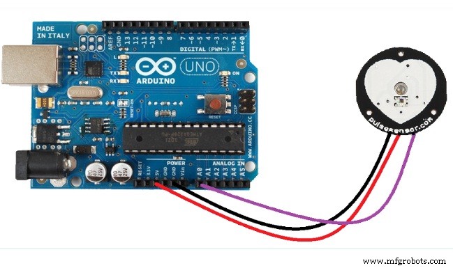
Connect the sensor’s VCC to +5 V (or +3.3 V) and GND to the Arduino ground. Then wire the signal output to an analog input pin. Use the Arduino PulseSensor library to read heart rate in real time; sample code and tutorials are available on the Arduino website.
Applications of Pulse Sensor
Because it delivers real‑time heart‑rate data, the Pulse Sensor is used in:
- Sleep tracking wearables
- Anxiety and stress monitoring devices
- Remote patient monitoring and alert systems
- Fitness bands and health trackers
- Interactive gaming peripherals
In summary, the Pulse Sensor is an open‑source, plug‑and‑play device that lets makers, students, and developers capture live heartbeat information. With its optical amplification and noise‑reduction circuitry, it’s a versatile component for projects ranging from health monitoring to creative installations.
Sensor
- Voltage Sensors: How They Work & Key Applications in Modern Power Systems
- RVG Sensor: How It Works and Why It’s Transforming Dental Imaging
- Lambda (Oxygen) Sensor: Function, Operation, and Key Automotive Applications
- Image Sensors: Types, Operation, and Practical Applications
- Gyroscope Sensors: How They Work and Their Key Applications
- Flame Sensors: How They Work and Key Applications in Fire Safety
- Sound Sensors: How They Work & Practical Applications
- Humidity Sensors: How They Work and Key Applications
- Understanding RTD Sensors: Principles, Accuracy, and Key Applications
- Rain Sensors Explained: How They Work & Key Applications