


BH1750 Ambient Light Sensor: Specs, Features, and Practical Applications
Light is essential for vision and, as an electromagnetic wave, delivers energy in discrete packets called photons. When photons strike a light‑sensing element, the energy is transferred to the sensor’s material, creating an electrical signal that reflects the intensity of the incident light. The BH1750 is a compact, low‑power digital ambient light sensor that translates that signal into readable lux values via I2C communication.
What Is the BH1750?
The BH1750 is a digital ambient light sensor built around a photodiode and a dedicated analog‑to‑digital converter (ADC). It communicates with microcontrollers through the I2C bus, drawing only 0.12 mA from a 2.4 V–3.6 V supply. The photodiode’s PN junction generates a current proportional to light intensity; an integrated op‑amp converts this current to voltage, and the on‑chip ADC outputs a 16‑bit lux value.
Block Diagram of the BH1750
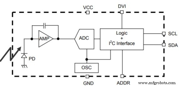
The diagram shows the photodiode (PD), the integrated op‑amp (AMP), the ADC, and the logic block that converts the ADC output into lux. An internal 320 kHz oscillator powers the I2C interface.
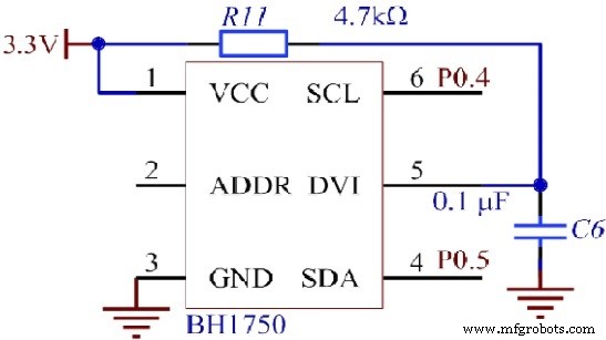
Operating Circuit
The BH1750 operates from 2.4 V to 3.6 V; the core BH1750FVI module requires 3.3 V, so a regulator is typically used. I2C pins (SDA, SCL) are pulled up with 4.7 kΩ resistors. The device offers three measurement modes:
- High‑Resolution Mode 2 – 120 ms conversion time, 0.5 lx resolution, optimal for low‑light environments with excellent noise rejection.
- High‑Resolution Mode – 120 ms conversion time, 1 lx resolution.
- Low‑Resolution Mode – 16 ms conversion time, 4 lx resolution.
Pin Diagram
- VCC – Power supply (2.4 V–3.6 V).
- GND – Ground.
- SCL – I2C clock line.
- SDA – I2C data line.
- ADDR – Address pin for multi‑device setups.
- DVI – Bus reference voltage; also serves as an asynchronous reset that must be powered down after VCC is applied.
Key Specifications
- Supply voltage: 2.4 V–3.6 V
- Operating current: 0.12 mA
- ADC resolution: 16‑bit
- Maximum measurable illuminance: 65 535 lx
- IR immunity: minimal impact on readings
- Light‑noise rejection: 50 Hz/60 Hz filtering
- Measurement range adjustable via internal registers
- Measurement variation: ±20 %
- Temperature range: –40 °C to 85 °C
- Minimum I2C reference voltage: 1.65 V
- I2C clock frequency: up to 400 kHz
Common Applications
- Adaptive backlight control in smartphones and tablets.
- Automatic headlight activation in automotive systems.
- Smart street‑light dimming.
- Ambient‑light based display brightness for LCDs and OLEDs.
- Photometric measurement in industrial sensors and IoT devices.
Alternatives
Other popular ambient‑light sensors include the TSL2561, VEML6035, and classic LDRs. For color detection, the TCS3200 is a common choice.
FAQ: Noise Rejection
Which BH1750 measurement mode offers the highest noise rejection? The High‑Resolution Mode 2 provides superior 50 Hz/60 Hz noise filtering and is best suited for low‑light or electrically noisy environments.
Datasheet
For detailed electrical characteristics and register maps, consult the official BH1750 datasheet.
Sensor
- 4 Key Applications of Hafnium: From Electronics to Aerospace
- Understanding IMU Sensors: Functionality and Applications in Modern Tech
- Inductive Sensors: How They Work and Key Industrial Applications
- ICM-20608-G: Compact 6‑Axis Motion Sensor for High‑Performance Applications
- APDS‑9960: A Multi‑Sensor IC for Gesture, Proximity, Light and Color Detection
- Color Sensors: How They Work & Key Applications
- Photoresistor (LDR): Function, Types, and Practical Applications
- Ambient Light Sensors: Functionality, Design, and Key Applications
- Piezoelectric Sensors: How They Work, Key Specs, and Arduino Integration
- Optical Sensors: Fundamentals, Types, and Practical Applications