

Industrial manufacturing
Industrial Technology


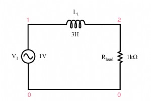
In earlier SPICE simulations we observed that a transformer’s output voltage can vary with changes in load resistance, even when the input voltage remains constant. Several factors influence this variance, including the inductances of the primary and secondary windings, winding resistance, and the d
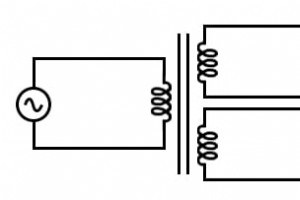
Transformers with Multiple Secondaries Transformers are remarkably versatile. While the classic single‑primary, single‑secondary design is widely taught, many practical applications benefit from additional secondary windings. Consider a transformer where three inductors share a common magnetic core,
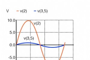
Why Phase Matters in Transformers Transformers are inherently alternating‑current (AC) devices, and the relative phase of the primary and secondary windings determines how voltage and current transfer between them. A clear grasp of these relationships is essential for both circuit designers and main
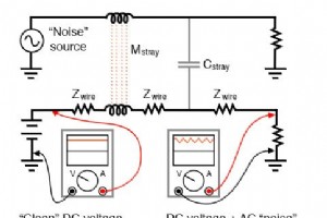
SPICE Analysis of Electrical Isolation Transformers not only enable voltage and current conversion in AC and DC circuits but also deliver a critical feature known as electrical isolation. This capability allows two circuits to be magnetically coupled without any direct wire connections, safeguarding

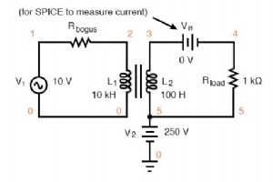
Previous sections illustrated transformer simulations where the primary and secondary windings had equal inductance, resulting in roughly equal voltage and current on both sides. When the inductances differ, the transformer behaves differently. transformer v1 1 0 ac 10 sin rbogus1 1 2 1e-12 rbog
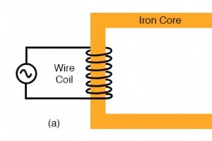
Behaviors of Inductors Wrapped Around a Conductive Core Imagine winding insulated copper wire around a ferromagnetic loop and energizing it with an AC source. The resulting iron‑core coil presents an inductive reactance that limits the AC current, just as any inductor does: XL = 2πfL and I = E/X (or
While this chapter has been extensive, it only scratches the surface of filter design. A quick glance at any advanced filter design textbook confirms this. The mathematics required for component selection and frequency‑response prediction can be daunting—far beyond the scope of a beginner. This guid
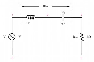
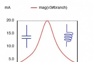
Up to this point, our filter designs have used either capacitors or inductors, but never both simultaneously. Combining L and C elements creates resonant behavior that can be harnessed to build precise band‑pass and band‑stop filters. Series LC circuits exhibit minimal impedance at their resonant fr
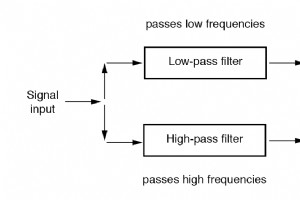
How to Build a Band‑Stop (Notch) Filter Band‑stop, or notch, filters suppress signals within a specified frequency band while allowing all lower and higher frequencies to pass. The most common topology pairs a low‑pass and a high‑pass section in parallel, mirroring the series connection used for ba
How to Create a Band‑Pass Filter In many electronic systems, only a specific range of frequencies must pass through a signal chain. A band‑pass filter lets precisely that band slip through while rejecting all lower and higher frequencies. By combining a low‑pass and a high‑pass stage, we obtain a
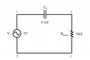
A high‑pass filter performs the inverse of a low‑pass filter: it permits high‑frequency signals to pass while attenuating low‑frequency components. The two most common implementations—capacitive and inductive—mirror their low‑pass counterparts but with opposite impedance behaviors. Capacitive high‑p
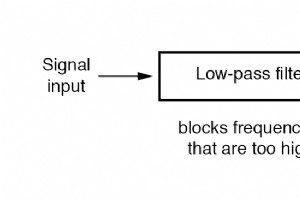
A low‑pass filter selectively allows low‑frequency signals to pass while attenuating higher frequencies. Two fundamental implementations—inductive and capacitive—form the basis of most passive filter circuits. Inductive Low‑Pass Filter The inductor’s impedance rises with frequency, presenting a hig
In many electronic systems, it is essential to isolate specific frequency components from a composite signal. A device engineered for this purpose is known as a filter circuit, or simply a filter. High‑end stereo systems routinely employ filters to boost or attenuate particular audio bands, enhancin
The principle that any periodic, non‑sinusoidal waveform can be decomposed into a set of sine waves of different frequencies is foundational in AC circuit analysis. When a circuit is driven by a waveform that is not a pure sine, the elements in the circuit respond as if a spectrum of frequency compo
Computer‑based Fourier analysis—particularly the Fast Fourier Transform (FFT) algorithm—is a cornerstone technique for dissecting waveforms into their spectral constituents. The same mathematical engine that powers SPICE’s .fourier feature is embedded in modern oscilloscopes and spectrum analyzers,
Every periodic, non‑sinusoidal waveform can be expressed as a sum of sinusoidal components—a principle known as Fourier series. While the square wave is the textbook example, real‑world power electronics routinely generate a wide array of complex shapes. Devices such as transistors and silicon‑contr
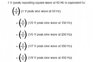
It has been found that any repeating, non-sinusoidal waveform can be equated to a combination of DC voltage, sine waves, and/or cosine waves (sine waves with a 90 degree phase shift) at various amplitudes and frequencies. This is true no matter how strange or convoluted the waveform in question may
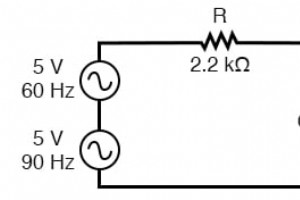
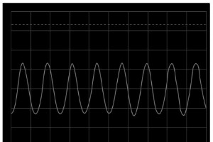
In our study of AC circuits, we have examined circuits powered by a single‑frequency sine voltage waveform. In many real‑world applications, however, single‑frequency signals are the exception rather than the rule. Often, circuits contain multiple frequency components simultaneously, and waveforms m
The Q, or quality, factor of a resonant circuit quantifies its selectivity and energy efficiency. A higher Q means a narrower bandwidth, which is crucial for filtering, tuning, and RF design. Mathematically, Q is the ratio of power stored in the reactive elements to power dissipated in the resistive
In ideal LC networks with negligible resistance, the resonance frequency is governed solely by the inductor and capacitor values, yielding either infinite impedance in a parallel (tank) circuit or zero impedance in a series configuration. However, once significant resistance is introduced, the simpl
Industrial Technology

Exploring the Pros and Cons of Equipment Tracking Software for Asset Management
Smart Shower Regulator - Reliable Solenoid Valve for Precise Temperature Control

DIY Ultrasonic Dog Repeller: Safely Keep Aggressive Dogs at Bay

A&P Technology Secures $8.9M Air Force Contract to Design Advanced Composite Aircraft Structures
