Industrial manufacturing
Industrial Technology

Resonance is far more than a laboratory curiosity; it is a powerful tool in AC circuit design. While some practitioners once viewed resonance merely as a nuisance—especially when series resonance creates a short‑circuit across an AC voltage source—modern engineers harness its unique properties for r

When the inductive and capacitive reactances in a series LC circuit match, their impedances cancel, driving the total impedance toward zero. This phenomenon, known as series resonance, causes the circuit to behave like a short at the resonant frequency. Below is a schematic of a simple series resona
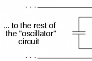
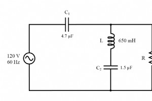
Resonance in a Parallel Tank Circuit In a parallel LC (tank) circuit, resonance is achieved when the inductive reactance (ÅXL = 2πfL) exactly equals the capacitive reactance (ÅXC = 1/(2πfC)). Because inductive reactance rises with frequency while capacitive reactance falls, only one frequency satisf
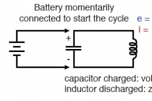
Capacitors store energy in the form of an electric field, and electrically manifest that stored energy as a potential: static voltage. Inductors store energy in the form of a magnetic field, and electrically manifest that stored energy as a kinetic motion of electrons: current. Capacitors and induc
While AC and DC circuit theory share foundational principles, AC analysis introduces complex quantities—voltages, currents, and impedances—instead of scalars. Ohm’s Law, Kirchhoff’s Laws, and network theorems developed for DC remain fully applicable when all parameters are expressed as complex numbe
What Is Conductance? In DC circuit analysis, the concept that serves as the inverse of resistance is called conductance. It becomes especially useful when simplifying networks of parallel resistors: R_{parallel} = 1 / (1/R_1 + 1/R_2 + … + 1/R_n) While adding resistors in parallel reduces the overall
Now that we’ve seen how series and parallel AC circuit analysis is not fundamentally different than DC circuit analysis, it should come as no surprise that series-parallel analysis would be the same as well, just using complex numbers instead of a scalar to represent voltage, current, and imp
We can rearrange the same resistor, inductor, and capacitor from a series circuit into a parallel arrangement, yielding the following example. Impedance in Parallel Components Connecting the components in parallel does not alter their individual impedances. With the same supply frequency, the ind
In this article we walk through a practical example of a series RLC circuit and show how to analyze it using complex impedance, Ohm’s law, and Kirchhoff’s voltage law. Series R, L, and C circuit. Step 1: Calculate Reactances First, compute the inductive and capacitive reactances: Step 2: Convert t
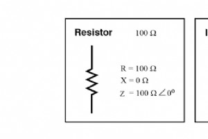
Before delving into how resistors, inductors, and capacitors behave together in alternating‑current (AC) networks, let’s recap the core concepts. Resistance Resistance is the electrical friction that opposes current flow. It is inherent in all conductors—except ideal superconductors—and is most comm
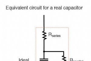
Like inductors, an ideal capacitor is a purely reactive element with no resistive, power‑dissipating component. In practice, however, capacitors tend to be far purer than inductors because their internal series resistance can be engineered to be very low. As a result, the impedance phase angle of a
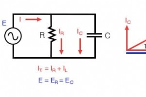
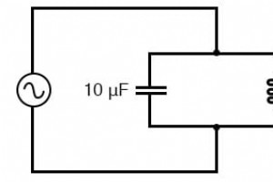
Building on the series example, we now connect the same resistor and capacitor in parallel to observe how AC behavior changes. Parallel R‑C circuit. Resistor and Capacitor in Parallel With the power source operating at the same frequency as in the series case, the resistor (R) and capacitor (C)
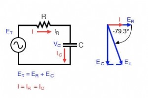
In the previous section we explored simple resistor‑only and capacitor‑only AC circuits. This article shows how combining these elements in series transforms the behavior. Series capacitor circuit: voltage lags current by 0° to 90°. Impedance Calculation The resistor provides a consta
Capacitors vs. Resistors Unlike resistors, which permit current proportional to the voltage drop, capacitors resist changes in voltage. They absorb or supply current as they charge or discharge to a new voltage level. Current flowing through a capacitor is directly proportional to the rate of change
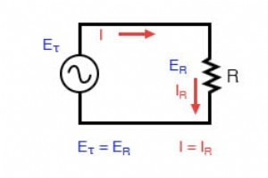
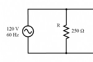
Pure resistive AC circuit: voltage and current are in phase. If we were to plot the current and voltage for a very simple AC circuit consisting of a source and a resistor, (figure above) it would look something like this: (figure below) Voltage and current “in phase” for
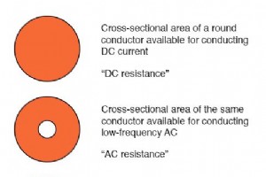
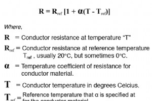
The Skin Depth of Copper in Electrical Engineering In alternating‑current (AC) systems, the skin effect causes current to concentrate near the surface of a conductor, effectively reducing the cross‑sectional area that carries current. This phenomenon raises the AC resistance above the DC value, espe
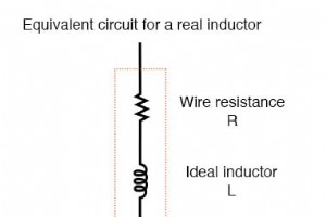
In an ideal world, an inductor would behave as a perfectly reactive component, offering only inductive reactance to AC. In practice, however, every inductor has measurable resistance, and its performance is influenced by several frequency‑dependent loss mechanisms. Because an inductor is built from
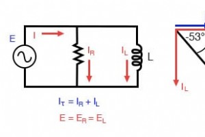
Using the same resistor and inductor from the series example, we now arrange them in parallel to explore AC behavior. Parallel R‑L circuit. Because the source frequency and component values remain unchanged, the individual impedances stay the same. We start our analysis with the following known val

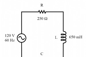
In the previous section we examined simple resistor‑only and inductor‑only AC circuits. Now we combine the two elements in series to explore how resistance and reactance interact and shape the overall circuit behavior. Series Resistor‑Inductor Circuit Example Consider the following schematic:
Resistors vs. Inductors Inductors behave quite differently from resistors. A resistor simply drops a voltage that is proportional to the current flowing through it. In contrast, an inductor resists changes in current by generating a voltage proportional to the rate of change of that current. This re
Industrial Technology