Industrial manufacturing
Industrial Technology

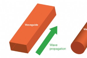
A waveguide is a specialized transmission line consisting of a hollow metallic tube. The metal walls provide distributed inductance, while the internal air gap supplies distributed capacitance. Waveguides conduct microwave energy with lower loss than coaxial cables. Waveguides are practical only fo
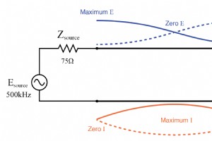
At the resonant frequency of a transmission line, standing waves arise that can dramatically alter the impedance perceived by the source. When the line length equals an integer multiple of half a wavelength (λ/2, λ, 3λ/2, …), the source “sees” the termination impedance unchanged. Illustrations below
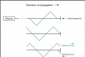
When an impedance mismatch occurs between a transmission line and its load, reflected waves arise. For a continuous AC source, the incident and reflected waves interfere to form stationary patterns known as standing waves. In the diagram below, a triangle‑shaped incident waveform is reflected at the

Understanding Long and Short Transmission Lines In DC and low‑frequency AC circuits, the characteristic impedance of parallel conductors is often ignored. This is especially true when coaxial cables are used to shield weak voltage signals from stray electric and magnetic noise. The reason is that th
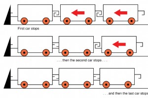
A transmission line of infinite length is a useful theoretical construct, but every real cable has a finite span, which changes its behaviour. When I measured a 50 Ω RG‑58/U cable with an ohmmeter years ago, the finite length caused the measurement to read “open” (infinite resistance). If the cable

The Parallel Wires of Infinite Length Consider a pair of parallel conductors extending to infinity, terminated with no load. When the source switch is closed, the line behaves as an open circuit. Does it draw any current at all? See the illustration below. Driving an infinite transmission line. Eve
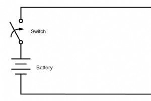
Consider a basic one‑battery, one‑lamp circuit controlled by a single switch. When the switch closes, the lamp appears to light instantly; when it opens, the lamp goes out immediately. The visible response is delayed by the filament’s heating time, but the underlying electrical effect occurs essenti
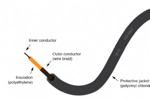
Why a 50‑Ω Coaxial Cable Behaves Like 50 Ω When Tested with AC, Not DC When I first encountered a length of coaxial cable labeled “50 Ω” on its outer sheath, I was puzzled. Coaxial cable is a two‑conductor system: a central conductor surrounded by a braided shield, with a dielectric separating the t
After arriving in America, Charles Proteus Steinmetz tackled the perplexing challenges of designing brushed AC commutator motors, which previously could not be reliably engineered before construction. His breakthrough came by formalizing magnetic hysteresis, revealing how the magnetic flux lags behi
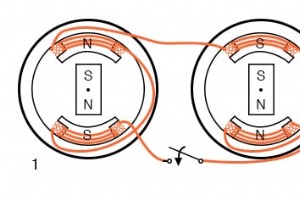
In most wound‑rotor induction motors, the rotor windings are shorted after the machine starts. During the start‑up phase, a series resistance limits the high inrush current. When two motors share a common starting resistance, they remain synchronized throughout the start‑up period. This feature is e

Shaded Pole Induction Motor Shaded‑pole induction motors generate starting torque by incorporating a shorted copper loop in each stator pole, positioned 30° to 60° from the main winding. Typically, one‑third of a pole is wrapped with a bare copper strap. The shading coils create a lagging, damped ma
Understanding Single‑Phase Induction Motors Single‑phase induction motors are ubiquitous in residential and light industrial applications, yet their operation differs significantly from their three‑phase counterparts. This article explains why a single‑phase motor cannot self‑start, outlines the var
A wound‑rotor induction motor features a stator identical to a squirrel‑cage motor, but its rotor contains insulated windings that exit through slip rings and brushes. While no power is ever supplied to the slip rings, they serve a crucial role during start‑up: they allow a series resistance to be i

Induction motors dominate the AC landscape, accounting for roughly 90% of industrial machines. Their resilience and straightforward construction make them the go-to choice for heavy‑duty drives. In 1883 Nikola Tesla laid out the fundamentals of the polyphase induction motor. By 1888 he had built a 0
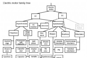
The advent of solid‑state power semiconductors enabled the transition from traditional brushed DC motors to brushless DC (BLDC) designs. Although BLDCs are DC devices, their operating principles closely mirror those of AC synchronous motors, making them relevant to any discussion of AC motor technol
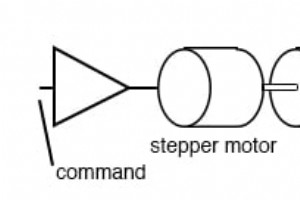
Stepper Motor vs Servo Motor A stepper motor is a digital motor that moves its rotor in discrete steps rather than rotating continuously. When energized but stopped, it holds its load with a reliable holding torque. The widespread adoption of stepper motors in the last two decades was made possible
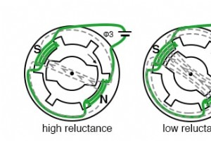
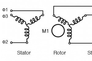
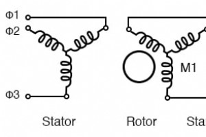
The variable reluctance motor operates on the principle that an unrestrained iron piece naturally moves to complete a magnetic flux path with minimal reluctance, the magnetic equivalent of electrical resistance. Synchronous Reluctance When the rotating field of a large synchronous motor with salient
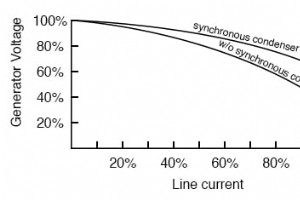
Synchronous motors operate with a leading power factor, a feature that effectively offsets the lagging power factor produced by induction motors and other inductive loads. Historically, large industrial synchronous motors were adopted mainly for this power‑factor correction capability. Overexciting
Single‑Phase Synchronous Motors Compact single‑phase synchronous motors are ideal for precision‑timing devices such as quartz clocks and tape players. While battery‑powered quartz clocks are ubiquitous, the AC‑line version offers superior long‑term accuracy because power‑plant operators actively mai
Following Thomas Edisons deployment of a DC distribution network across the United States, industry gradually shifted toward the more cost‑effective AC system, with lighting performance on AC matching that on DC. AC proved superior for long‑distance power transmission, reducing losses. Yet early att
Industrial Technology