Industrial manufacturing
Industrial Technology

In modern automation, accurately converting mechanical motion into electrical signals is essential. While DC-based devices such as thermocouples and strain gauges have long served this purpose, AC transducers offer unique advantages—especially when contactless operation, high precision, and safety a

Just as DC bridge circuits enable accurate resistance measurement, AC bridge circuits extend this principle to determine unknown impedances—resistive, capacitive, and inductive—using balanced voltage dividers and a sensitive null detector. How Does a Bridge Circuit Work? A bridge circuit consists o
Historically, the term power quality was largely limited to power factor in large AC power systems. Today, the proliferation of nonlinear electronic loads—such as variable-frequency drives, power supplies, and LED lighting—introduces significant harmonic distortion, turning once‑clean sine‑wave volt
Measuring power in AC circuits is inherently more complex than in DC because phase shifts mean that simply multiplying voltage and current readings does not reflect true power.What is required is an instrument that can determine the product of instantaneous voltage and current. The classic electrody
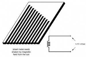
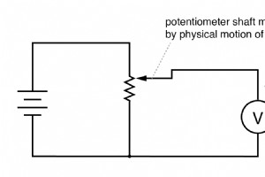
Frequency is a uniquely AC property, crucial for systems that must operate at a precise rate—typically 50 Hz in Europe or 60 Hz in North America. While a generator’s shaft speed can directly give frequency in a local setting, remote measurement demands more sophisticated techniques. Mechanical Reson

Electromechanical meter movements for alternating current are generally divided into two groups: adaptations of direct‑current (DC) designs and units specifically engineered for AC measurement. Permanent‑magnet moving‑coil (PMMC) movements cannot be connected directly to AC. The needle would oscilla

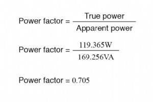
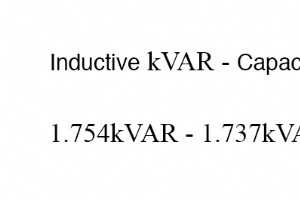
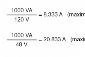
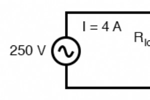
When an AC system exhibits a low power factor, you typically cannot rely on precise inductance values for corrective calculations. If available, a power‑factor meter provides the instantaneous power‑factor value (between 0 and 1) and the apparent power, which is obtained by multiplying the measured
The phase angle shown in the classic power‑triangle diagram is the key to understanding how efficiently an AC circuit uses electrical energy. It represents the ratio between the real (or true) power that does useful work and the apparent power drawn from the supply. In polar form, the same angle des
Reactive Power In alternating‑current circuits, inductors and capacitors do not dissipate energy—they merely store and release it. Yet because they draw current while dropping voltage, they can appear to consume power. This apparent consumption is known as reactive power and is quantified in Volt‑Am
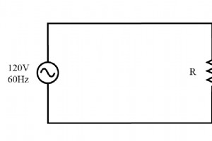
In a single‑phase 120‑V, 60‑Hz AC system, a purely resistive load draws 2 A (RMS) and dissipates 240 W. Because the load has no reactance, the voltage and current waveforms are in phase, and the power waveform is always positive. Below is a schematic of the basic resistive circuit: When you plot
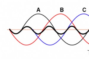
In the previous section we showed that the third harmonic and its integer multiples—known as triplen harmonics—generated by 120° phase‑shifted fundamental waveforms are actually in phase with one another. In a standard 60 Hz three‑phase system, where phases A, B, and C are spaced 120° apart, the thi
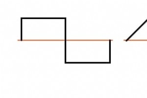
Harmonics—integer multiples of the fundamental frequency—are a natural consequence of non‑linear load behavior in AC power systems. Although a clean sine wave from a generator ideally contains no harmonic content, real‑world devices distort this waveform, generating measurable harmonic currents that
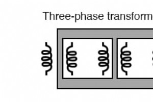
Three‑phase power is the backbone of modern electric grids, and the transformers that step its voltage up or down are equally critical. While a single‑phase transformer can be ganged together to bridge two three‑phase systems, dedicated three‑phase transformers offer a more efficient solution—using
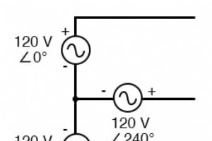
Three‑Phase Wye (Y) Connection Three‑phase power systems can be built by joining three voltage sources at a common point – the classic Y (or star) configuration. This arrangement places one end of each source on a shared node, while the other ends radiate to the load. (Figure below) Three‑phase Y c
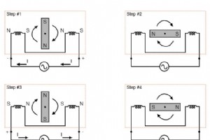
AC Motors Polyphase AC power provides a clear advantage in motor design over single‑phase: the ability to generate a naturally rotating magnetic field. Many AC motors—both induction and synchronous—mirror the construction of their alternator counterparts, featuring stationary windings that energize
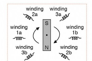
Three‑Phase Alternator Let’s revisit the three‑phase alternator design we discussed earlier and observe the effects of magnet rotation on the generated voltages. Three‑phase alternator The 120° phase shift is a direct result of the actual angular displacement of the three winding pairs. If the magn
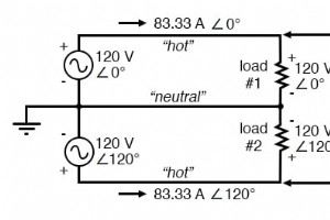
What is Split‑Phase Power? Split‑phase systems enhance conductor efficiency while reducing safety risks by dividing the total voltage into lower levels. Each load operates at a reduced voltage, yet the currents remain typical of a full‑voltage system. While the term “phase” is strictly an AC concept
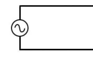
Illustration of a single‑phase power system. The schematic highlights key wiring considerations for real‑world applications. Below is a very simple AC circuit. When the load resistor dissipates a substantial amount of power, we refer to this as a “power circuit” or “power system” rather than a gene
Power Capacity Transformers must be engineered for robust power coupling, tight voltage regulation, and minimal exciting‑current distortion. Proper conductor gauge prevents overheating during the expected primary and secondary currents. Ideal Transformer In theory, an ideal transformer offers perfec
Impedance Matching Transformers can step voltage and current between primary and secondary windings, enabling the conversion of a load’s impedance to a level that matches the source. This capability is critical for efficient power transfer and is widely employed in industrial, audio, and power‑distr
Industrial Technology