Industrial manufacturing
Industrial Technology

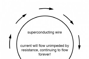
When a conductor is cooled to temperatures near absolute zero—around –273 °C—it can lose all electrical resistance, not just a small fraction. This abrupt transition to zero resistance, rather than a gradual decline, is the hallmark of superconductivity. H. Kamerlingh Onnes first observed this effec
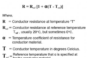
When you look at a standard resistance table, you’ll notice every value is quoted at 20 °C. That’s because a material’s specific resistance changes with temperature. If you need the resistance of a conductor at a different temperature, you must apply the temperature‑coefficient formula. The Greek s
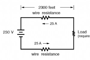
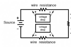
When designing electrical circuits, ampacity ratings only address fire safety, not voltage drop. In many applications—especially power‑supply designs—the voltage that reaches a load must not fall below a specified threshold. A conductor’s resistance can introduce a voltage drop that, while far below

While the ampacity rating of a conductor is typically a design limit that should never be exceeded, fuses are an exception. In these devices the very design is to surpass the rated current and then safely interrupt the circuit. What Is a Fuse? A fuse is an electrical safety device that contains a co

The smaller the cross‑sectional area of a conductor, the higher its resistance for a given length, all else being equal. Higher resistance means more heat generated for the same current, as shown by the power equation P = I2R. This heat can damage the wire and nearby materials, especially since most
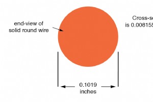
Understanding Conductor Size In electrical engineering, the ease with which electrons flow through a conductor is governed largely by the conductor’s cross‑sectional area. Just as a larger straw allows liquid to pass more readily than a narrow one, a thicker wire provides a greater path for electron
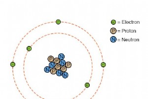
Fundamental Concepts of Electrical Conductivity Electrical conductivity depends on how freely electrons can move within a material. Materials that allow electrons to travel easily are called conductors, while those that restrict electron motion are called insulators. Classical “planetary” models of
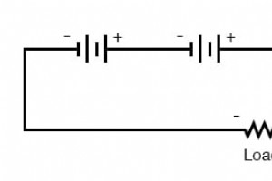
When building larger battery banks, selecting compatible cells is essential to avoid capacity loss and safety hazards. Batteries in Series Connecting cells in series raises the overall voltage while keeping the amp‑hour capacity unchanged. Because the same current flows through every cell, all cells

Special‑Purpose Batteries In the formative years of electrical measurement, the mercury standard cell served as the benchmark for voltage calibration. Delivering a highly stable output of 1.0183–1.0194 V DC, these cells were prized for their minimal drift—about 0.004 % of rated voltage per year. The
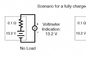
Batteries generate current by exchanging electrons in ionic reactions. Because the number of reactable molecules is finite, a battery can only deliver a limited amount of charge before its energy reserves are depleted. While it’s theoretically possible to measure capacity by counting electrons, the
The term battery denotes a group of similar components. In military jargon it refers to a cluster of guns; in electronics it describes a set of voltaic cells combined to deliver higher voltage and/or current than a single cell can provide. Electrical symbols are intentionally simple: a single cell i
While earlier chapters introduced the atom and its constituent particles—electrons, protons, and neutrons—this section dives into the practical side of batteries. We explore the chemistry that turns chemical energy into electrical energy, and examine the real-world considerations for power systems.
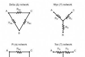
In many practical circuits, components are arranged as either a Δ (delta) or a Y (wye) network. These configurations are ubiquitous in power systems, signal processing, and network design. By determining the appropriate resistor values, a Δ network can be made electrically indistinguishable from a
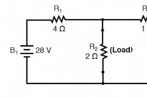
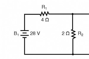
The Maximum Power Transfer Theorem is a cornerstone of electrical engineering that informs how designers deliver optimal power to a load. In practice, the greatest power dissipation occurs when the load resistance equals the Thevenin or Norton resistance of the source network. In radio transmitter d
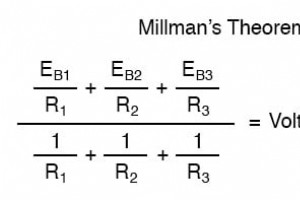
Ever wondered how the seemingly complex formula for the “Millman voltage” is derived? It’s all about treating each parallel branch—each consisting of a series resistor and voltage source—as a Thevenin equivalent and then converting those to Norton equivalents. The resulting expression is simply the
Since Thevenin’s and Norton’s Theorems both simplify complex networks into manageable equivalents, it is natural to convert a Thevenin equivalent into a Norton equivalent—and vice versa—using a straightforward procedure. Thevenin Resistance and Norton Resistance Both Thevenin and Norton resistances
What is Norton’s Theorem? Norton’s Theorem shows that any linear circuit—regardless of complexity—can be reduced to an equivalent circuit composed of a single current source in parallel with a resistance. The term “linear” carries the same meaning as in the Superposition Theorem: all relationships

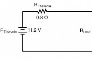
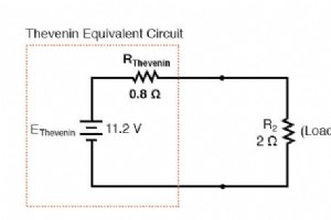
In electrical engineering, Thevenin’s Theorem guarantees that any linear network—composed of resistors, inductors, capacitors, and ideal sources—can be collapsed into an equivalent circuit with a single voltage source in series with a resistance. This reduction is invaluable when evaluating the effe
The Superposition Theorem offers a straightforward method for evaluating linear electrical networks by isolating one source at a time. By treating each power source independently, we can determine voltage and current contributions that are then algebraically combined to reveal the behavior of the co

Millman’s Theorem offers a quick way to determine the common voltage across a set of parallel branches, each containing a voltage source and a series resistance. The theorem applies only to circuits that can be redrawn as a parallel network of such branches. Below we use the same example circuit fro
Industrial Technology