Industrial manufacturing
Industrial Technology

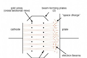
Beam power tubes build upon the classic tetrode architecture by integrating a pair of auxiliary plates and a meticulously arranged grid‑screen system. The result is a focused electron beam—or “sheet”—that travels from cathode to plate with exceptional precision. Inside the tube, the electrons form a

The tetrode tube, named for its four key elements—cathode, grid, screen, and plate—represents a significant evolution in vacuum‑tube technology. Its design builds upon the triode by adding a screen grid that dramatically improves performance in amplifier circuits. Unlike the triode, the screen grid

The Triode: A Cornerstone of Vacuum Tube Technology Guglielmo Marconi’s early radio experiments set the stage for the first practical vacuum tubes, the Audion tubes pioneered by Lee de Forest. De Forest’s Audion earned the moniker triode because it contained three key components: a filament (electr
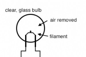
Thomas Edison is often credited with inventing the incandescent lamp, but he was the pioneer who refined the design that would later power modern electronics. In 1879, Edison’s successful lamp used a carbonized sewing thread filament inside a glass bulb from which air had been removed. The resulting
Vacuum tubes—also called electron tubes—were the bedrock of the first electronic circuits that powered radio, television, and early computers. Though largely supplanted by solid‑state devices, understanding tubes offers invaluable insight into the principles that underpin modern electronics.At their
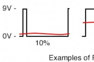
Pulse Width Modulation (PWM) employs precise digital waveforms to regulate power delivery, offering a low‑hardware path to analog signals. In linear power supplies, heat is a major drawback because variable resistors must carry substantial current continuously. Digital switching devices, on the othe
Control Circuits: Fundamentals, Applications, and Best Practices Control circuits are the backbone of modern industrial automation, enabling precise, reliable operation of machinery, safety systems, and process controls. They translate user inputs or sensor signals into mechanical actions, light ind
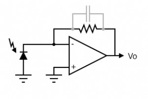
For accurate low‑light detection, a trans‑impedance (current‑to‑voltage) amplifier is preferred over a conventional op‑amp. This configuration delivers superior sensitivity and bandwidth. The photodiode is reverse‑biased to minimize its capacitance, which in turn expands the bandwidth and suppresses
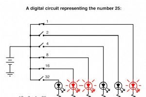
When the word “computer” comes up, most people picture a digital device that processes information in binary—discrete 1’s and 0’s—using countless transistors that toggle between saturation and cutoff. Yet analog circuitry can represent and manipulate numerical values with continuous volt

(a) Crystal radio. (b) Modulated RF at antenna. (c) Rectified RF at diode cathode, without C2 filter capacitor. (d) Demodulated audio to headphones. The core of a crystal radio consists of an antenna, a ground connection, a tank circuit (C1 and L1), a peak detector, and headphones. The antenna captu
What Is a Phase‑Locked Loop? A Phase‑Locked Loop (PLL) is an electronic circuit that synchronizes an output signal’s phase and frequency to a reference signal. It’s the backbone of modern digital communications, clock generation, and frequency synthesis. Core Components Phase Detector (PD) – Measur
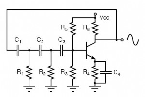
Phase shift oscillator. Each RC stage (R1C1, R2C2, R3C3) contributes a 60° phase shift. The oscillator depicted above produces a pure sine wave in the audio band. While the collector provides a 180° phase inversion, the three cascaded RC phase shifters add another 180°, yielding a total 360° shift.
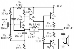
In this push‑pull configuration, Q3 is an NPN transistor while Q4 is its complementary PNP counterpart. The complementary pairing delivers a balanced, low‑distortion output, making the stage well suited for moderate‑power audio applications. The design is fully directly coupled, which simplifies bia
Power supplies come in several standard configurations, each with distinct trade‑offs in cost, size, efficiency, and output stability. Understanding the fundamentals of unregulated, linear regulated, switching, and ripple‑regulated designs is essential for selecting the right solution for a given ap
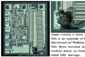
At the beginning of this discussion we examined static electricity and its creation. Controlling static is far more critical than it first appears— it underpins the reliability of today’s electronics and many other high‑precision fields. An Electrostatic Discharge (ESD) event occurs when a static ch
All semiconductor op‑amp models (excluding the CA3130) are sourced from National Semiconductor’s official online repository, accessible via this link. The CA3130 specifications are taken from Harris Semiconductor’s CA3130/CA3130A datasheet (file no. 817.4).

When most people think of operational amplifiers, they imagine silicon‑based ICs. However, the earliest commercial op‑amps were vacuum‑tube circuits. In 1952, George A. Philbrick Researches, Inc. introduced the K2‑W, the first general‑purpose op‑amp. It featured two twin‑triode tubes housed in an oc
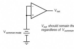
Real operational amplifiers deviate from the ideal model in several ways: input offset, finite common‑mode rejection, input bias currents, temperature drift, and frequency‑dependent gain and phase. Understanding these non‑idealities is essential for designing robust analog circuits. While many error
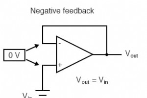
While negative feedback is essential for tuning op‑amp gain, bandwidth, and stability, positive feedback offers its own unique advantages. By feeding the output back to the non‑inverting input, an op‑amp can lock into one of two saturated states, creating hysteresis that is invaluable in comparator
By incorporating electrical reactance into the feedback loop of an op‑amp, the output can be made to respond to changes in the input voltage over time. Drawing their names from the corresponding calculus operations, the integrator produces a voltage proportional to the product of the input voltage a
Industrial Technology