Industrial manufacturing
Industrial Technology

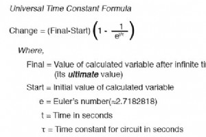
Time Constant in Series RC and RL Circuits In a series RC circuit, the time constant (τ) is the product of the resistance (R) and capacitance (C). In a series RL circuit, τ is the ratio of inductance (L) to resistance (R). τ (seconds) = R × C τ (seconds) = L ÷ R Determining Voltage or Current at a
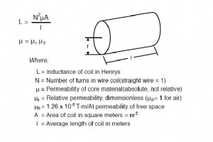
Inductance Fundamentals The following image illustrates the core concepts behind Wheeler’s inductance equations. Wheeler’s formulas are the industry standard for estimating the inductance of air‑core coils, especially at radio frequencies. They provide reliable results with an accuracy of about 1 %
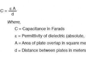
Capacitance Formula The capacitance of a parallel‑plate capacitor is calculated with the well‑known relationship: Permittivity of Dielectric Dielectric permittivity (εr) is a material property that determines how much charge a capacitor can store at a given voltage. It scales the capacitance linea

Series and Parallel Resistances When resistors are connected end‑to‑end, the total resistance is the arithmetic sum: Series: Req = R1 + R2 + … + Rn In a parallel arrangement, each resistor shares the same two nodes, reducing the overall resistance. The reciprocal of the equivalent resistance equals
Voltage In a parallel circuit, every component is exposed to the same source voltage. This means that the voltage across each branch is equal to the total source voltage: Etotal = E1 = E2 = … = En Resistance The combined resistance of parallel elements is always lower than any individual resistanc
Current in a Series Circuit In a series connection every component experiences the same current. Therefore the total current equals the current through each element: Itotal = I1 = I2 = … = In Resistance in a Series Circuit The overall resistance is simply the sum of all individual resistances, whi
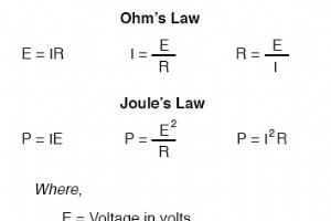
Power Equation of Ohm’s Law and Joule’s Law Note: The symbol V (often U in Europe) is frequently used to denote voltage instead of E. In many texts, designers use V exclusively for voltage, while E may represent the source voltage and V the voltage drop across a load. The symbols can also be inte
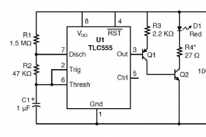
Components & Materials 2 × AAA batteries (fresh alkaline recommended) Battery clip (Radio Shack #270‑398B) Digital multimeter or voltage‑only meter U1 – CMOS TLC555 timer IC (RS #276‑1718 or equivalent) Q1 – 2N3906 PNP transistor (RS #276‑1604 or equivalent) Q2 – 2N2222 NPN transistor (RS #276‑1617
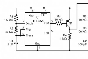
Parts & Materials Two AAA Batteries Battery Clip (Radio Shack catalog # 270-398B) U1, U2 – CMOS TLC555 timer IC (Radio Shack catalog # 276-1718 or equivalent) Q1 – 2N3906 PNP Transistor (Radio Shack catalog # 276-1604 (15 pack) or equivalent) Q2 – 2N2222 NPN Transistor (Radio Shack catalog # 276-16
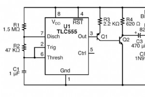
Components & Materials 2 × AAA batteries Battery clip (Radio Shack #270‑398B) U1 – 1 CMOS TLC555 timer IC (Radio Shack #276‑1718 or equivalent) Q1 – 2N3906 PNP transistor (Radio Shack #276‑1604 or equivalent) Q2 – 2N2222 NPN transistor (Radio Shack #276‑1617 or equivalent) CR1 – 1N914 diode (Ra
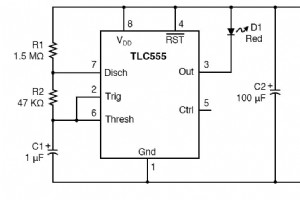
PARTS AND MATERIALS Two AAA batteries Battery clip (Radio Shack catalog #270-398B) One digital multimeter (DVM) or voltage–current meter (VOM) U1 – CMOS TLC555 timer IC (Radio Shack catalog #276-1718 or equivalent) D1 – Red LED (Radio Shack catalog #276-041 or equivalent) R1 – 1.5 MΩ, ¼ W, 5 % resi
Building a 555 Monostable Multivibrator This beginner‑friendly tutorial walks you through the simplest 555 timer circuit, the monostable multivibrator. You’ll learn how the 555’s internal flip‑flop controls a single‑pulse output, how to calculate the timing interval, and why the design is immune to
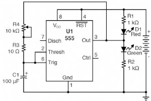
PARTS AND MATERIALS 1 × 9 V battery Battery clip (Radio Shack catalog # 270‑325) Mini hook clips (soldered to the battery clip, Radio Shack catalog # 270‑372) U1 – 555 timer IC (Radio Shack catalog # 276‑1723) D1 – Red LED (Radio Shack catalog # 276‑041 or equivalent) D2 – Green LED (Radio Shack ca
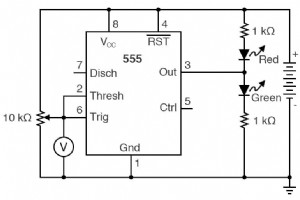
Build a 555 Timer Schmitt Trigger: Hands‑On Circuit & Theory What You’ll Need 1 × 9 V battery Battery clip (Radio Shack #270‑325) Mini hook clips, soldered to the battery clip (Radio Shack #270‑372) 1 × 10 kΩ, 15‑turn potentiometer (Radio Shack #271‑343) 1 × 555 timer IC (Radio Shack #276‑1723) 1 ×
The 555 integrated circuit remains the most iconic and widely used timer IC in electronics history. Over 40 years old and still in mass production by more than ten manufacturers, its enduring popularity is a testament to its robust design and versatility. Developed in 1970 by Hans R. Camenzind and i
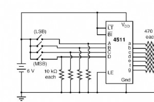
Parts & Materials 4511 BCD‑to‑7seg latch/decoder/driver (Radio Shack catalog # 900‑4437) Common‑cathode 7‑segment LED display (Radio Shack catalog # 276‑075) Eight‑position DIP switch (Radio Shack catalog # 275‑1301) Four 10 kΩ resistors Seven 470 Ω resistors One 6 V battery ⚠️ Caution: The 4511 I
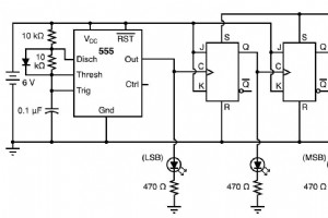
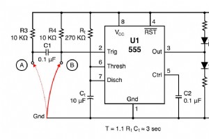
3‑Bit Binary Counter with 555 Timer and 4027 Flip‑Flops Parts & Materials 555 timer IC (Radio Shack catalog # 276‑1723) 1N914 “switching” diode (Radio Shack catalog # 276‑1122) Two 10 kΩ resistors 100 µF capacitor (Radio Shack catalog # 272‑1028) 4027 dual J‑K flip‑flop (Radio Shack catalog # 900‑4
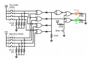
Designing a 4‑Bit Combination Lock with XOR & NOR Gates Parts & Materials 4001 quad NOR gate (Radio Shack catalog # 276-2401) 4070 quad XOR gate (Radio Shack catalog # 900-6906) Two, eight-position DIP switches (Radio Shack catalog # 275-1301) Two light-emitting diodes (Radio Shack catalog # 276-02
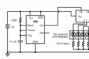
PARTS AND MATERIALS 4017 decade counter/divider (Radio Shack catalog # 276-2417) 555 timer IC (Radio Shack catalog # 276-1723) Ten‑segment bargraph LED (Radio Shack catalog # 276-081) One SPST switch One 6‑volt battery 10 kΩ resistor 1 MΩ resistor 0.1 µF capacitor (Radio Shack catalog # 272-135 or
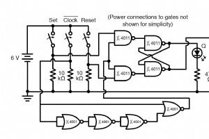
PARTS AND MATERIALS 4011 quad NAND gate (Radio Shack catalog # 276-2411) 4001 quad NOR gate (Radio Shack catalog # 276-2401) Eight‑position DIP switch (Radio Shack catalog # 275-1301) Ten‑segment bar graph LED (Radio Shack catalog # 276-081) One 6 V battery Three 10 kΩ resistors Two 470 Ω resistors
Industrial Technology