

Industrial manufacturing
Industrial Technology


The Rules of Binary Addition Adding binary numbers is straightforward, mirroring the long‑hand addition of decimal figures. Start from the rightmost column (the least significant bit) and move left, adding each pair of bits. Unlike decimal addition, binary has a minimal set of rules: 0 + 0 = 0 1 +

The numeration system chosen to represent a number does not alter the results of any arithmetic operation—addition, subtraction, multiplication, division, roots, powers, or logarithms remain consistent. A number remains the same regardless of its representation. For instance, one plus one always equ
While binary, octal, and hexadecimal systems are deeply rooted in computer science, most people are most comfortable with the decimal system. Converting from decimal to these non‑decimal bases may feel daunting, but with a clear methodology it becomes straightforward. Trial‑and‑Fit Method The trial‑

While octal and hexadecimal systems primarily serve as compact representations of binary in digital electronics, there are frequent scenarios where converting these numbers to decimal format is essential. Instead of the two-step process—converting to binary first and then to decimal—you can transfor
Binary representation is the native language of digital circuits, but its dense strings of 0s and 1s can make debugging and design laborious. To streamline communication among engineers, technicians, and programmers, we use base‑8 (octal) and base‑16 (hexadecimal) systems, both of which convert effo
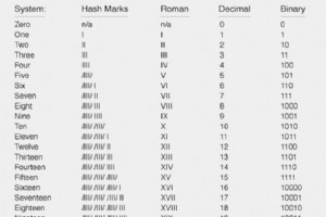
Counting from zero to twenty is straightforward in many numeration systems. Below, we illustrate the same sequence using four different styles: hash marks, Roman numerals, decimal, and binary. Hash marks and Roman numerals are simple, but they become unwieldy when representing larger values. In c
Roman Numerals Roman numerals represent numbers using a set of symbols that evolved to convey larger quantities more efficiently than earlier tally marks. The basic symbols and their values are: I = 1 V = 5 X = 10 L = 50 C = 100 D = 500 M = 1000 When a symbol is followed by one of equal or lesser
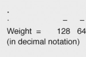
The expression of numerical quantities is something we tend to take for granted. This is both a good and a bad thing in the study of electronics. It is good, in that we’re accustomed to the use and manipulation of numbers for the many calculations used in analyzing electronic circuits. On the
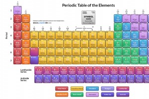
Periodic Table – Portrait View Comprehensive periodic table of chemical elements.
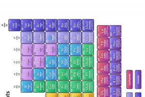
Periodic table of chemical elements. The periodic table arranges all known chemical elements by atomic number, electron configuration, and recurring chemical properties, offering a visual map of the building blocks of matter. Discover how elements are grouped into periods and families, and ho
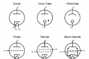
Electron tubes, or vacuum tubes, form the backbone of many legacy and high‑end audio and radio systems. Their operation hinges on a handful of carefully engineered electrodes that control electron flow. Cathode: The heated electrode that emits electrons through thermionic emission. Anode: A high‑p
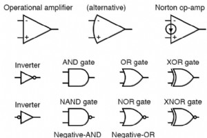
Logic Gates: The Fundamental Building Blocks of Digital Systems A logic gate is a fundamental electronic component that implements Boolean logic functions, transforming binary input signals into a single binary output. Each gate operates on discrete voltage levels that represent logical HIGH
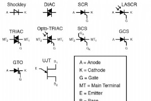
A thyristor is a solid‑state device that offers a range of distinctive features. It has three terminals—anode, cathode, and gate—reminiscent of thermionic valves and vacuum tubes.The gate is the control terminal; the main current flows between the anode and cathode.The DIAC symbol consists of two tr
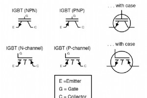
The hybrid configuration couples an insulated‑gate field‑effect transistor (IGFET) to a bipolar junction transistor (BJT). The IGFET, acting as a high‑impedance gate, drives the base of the BJT without drawing current from the control circuitry. Consequently, the system delivers a very high current
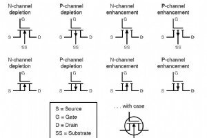
Insulated‑Gate Field‑Effect Transistors (IGFETs), commonly called MOSFETs, are the backbone of modern digital and power circuits. Understanding how their gate voltage controls the conductive channel is essential for reliable design. In the diagram above, the two symbols—one with a solid line and on
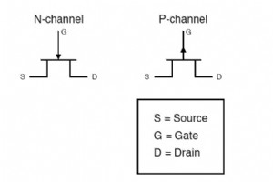
In a junction field‑effect transistor, the arrow on the gate symbol tells you the direction of the gate current when the gate junction is forward‑biased. N‑channel JFET: The arrow points into the device, indicating that the gate current flows toward the channel. P‑channel JFET: The arrow points aw
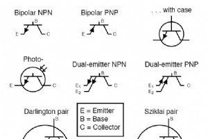
Bipolar Junction Transistors (BJTs) are a cornerstone of analog and digital electronics. Their circuit symbols are simple yet highly informative. Two main families exist: NPN and PNP. The symbol for each is identical except for the direction of the arrow on the emitter leg, indicating the conventio
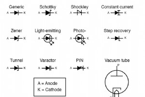
Diodes: Fundamentals, Construction, and ApplicationsA diode is a semiconductor device comprising a p‑type and an n‑type region joined at a p‑n junction. Two metal leads attach to the junction, enabling straightforward integration into electronic circuits.The lead attached to the n‑type material is t
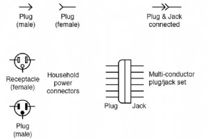
Electrical connectors are essential electro‑mechanical components that enable reliable power and signal transfer between devices. They form the backbone of modern electronic systems, ensuring that circuits can be built, modified, and maintained with precision. At their core, connectors comprise a m
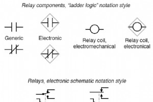
At the heart of every programmable logic controller (PLC) is ladder logic – a programming paradigm that traces its roots back to the electrical ladder diagrams that once guided relay panels in industrial automation. These diagrams were meticulously drawn to show how coils, contacts, and other devic
Industrial Technology
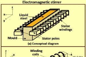
Improving Steel Quality with Contactless Electromagnetic Stirring in Continuous Casting

Reversing a Gear Pump: How to Transfer Fluid to Higher Pressure

Understanding PLA Conductivity: Electrical Properties of 3D Printing Filament
KUKA Cutting Robots: Unmatched Versatility for Laser, Plasma, Water‑Jet, and More
