

Industrial manufacturing
Industrial Technology

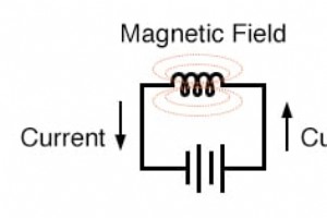
Electricity and Magnetism When an electric current flows through a conductor, it generates a magnetic field that circles the conductor. If the conductor is wound into a coil, the magnetic field aligns along the coil’s axis. The stronger the current, the stronger the magnetic field, all else equal.
In an ideal scenario, a mechanical switch should close instantly, creating a continuous electrical path as soon as the contacts meet. In reality, however, the moving contact’s mass and the inherent elasticity of the switch mechanism cause a brief “bounce” when the contacts first meet. This oscillat
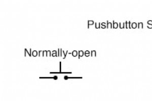
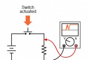
In process automation, a switch’s “normal” position is the state it occupies when no external force is applied – the position it would be in when mounted on a shelf, ready for operation. Switch contacts are engineered to either close (create continuity) or open (interrupt continuity) when actuated.

A switch’s primary function is to reliably connect and disconnect two conductors on command. The elements that make and break this electrical path are called contacts. While the underlying principle can be as simple as a lever forcing two copper wires together, a truly dependable switch design deman

While switches are foundational to electrical systems, a deep understanding of their types is essential for the chapters that follow—those that examine the mechanical switch‑based digital logic of earlier technology. Studying switch‑driven circuits alongside solid‑state logic gates simplifies both c
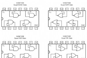
Digital logic gates are fabricated as integrated circuits—transistors and resistors etched onto a single semiconductor wafer. For engineers, technicians, and hobbyists who need a small number of gates, the Dual Inline Package (DIP) remains the most accessible and cost‑effective solution. DIP ICs fea
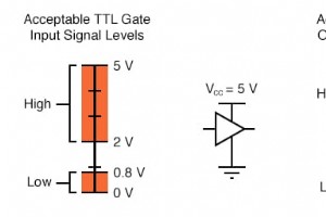
Input Voltages for Logic Gates Logic circuits are designed to operate with two discrete voltage levels that represent binary values: a high (logic 1) close to the supply voltage and a low (logic 0) near ground. In an ideal world these levels would sit exactly at the supply rails, but real‑world tran
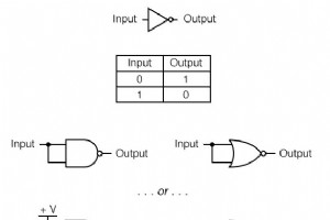
NAND and NOR gates are the only standard logic families that can, by themselves, implement any other logic operation when combined in sufficient numbers. This universal property is the foundation of many digital control systems that rely exclusively on one of these gate types. For instance, a simple
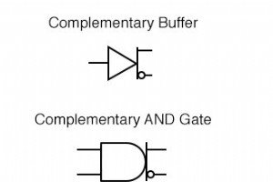
Complementary Output GatesIn many designs, engineers need a gate that delivers both inverted and non‑inverted outputs from a single logic element. A classic example is a one‑input buffer that also acts as an inverter, providing separate terminals for each function.Two‑input gates that simultaneously
Up until this point, our analysis of transistor logic circuits has been limited to the TTL design paradigm, whereby bipolar transistors are used, and the general strategy of floating inputs being equivalent to “high” (connected to Vcc) inputs—and correspondingly, the allowance of “open‑collector” ou

TTL Circuit Analysis Let’s analyze a classic TTL NOR gate and see how it can be transformed into an OR gate. The circuit below illustrates the key components: Transistors Q1 and Q2 serve as two‑diode steering networks, much like the steering network used in other TTL designs. Replacing them with ex
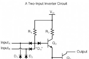
By adding a second input to a standard open‑collector TTL inverter, we obtain a circuit that naturally implements a NAND function. In this article we walk through the analysis, explain the underlying transistor behavior, and show how a simple inverter can be turned into an AND gate by adding one mor

The Use of Logic Gates Inverter and buffer circuits cover the entire range of single‑input logic operations. To add real functional depth, we expand the input count, thereby increasing the possible input states and enabling more complex logic behaviour. With a single input there are only two states:
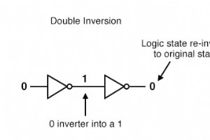
When two inverter gates are cascaded—output of one feeding the input of the second—the two inversions cancel, producing a non‑inverting path. Though this might appear redundant, it serves a critical role: amplifying weak signals. In TTL logic, every gate acts as a signal amplifier. A weak source th

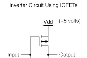
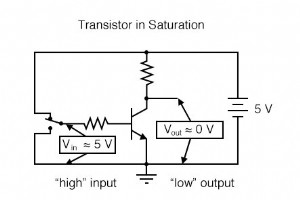
A single‑transistor inverter, while illustrative, lacks the performance required for real digital logic. Practical NOT gates employ multiple transistors to achieve high voltage gain, ensuring that the output transistor operates cleanly in either full cutoff or full saturation, and incorporate protec
Although binary numeration is a fascinating mathematical construct, its true power emerges when applied to electronics. This chapter demonstrates how binary bits translate into real‑world circuit behavior. The significance of binary numeration lies in its simplicity: a bit can only assume two values

Mastering the binary numbering system is essential for anyone designing, building, or troubleshooting digital circuits. The binary language—comprising only two values—maps directly onto the two transistor states of a circuit: saturated (on) and cut‑off (off). This natural fit makes binary the defaul

When working with signed binary numbers, an addition or subtraction can sometimes exceed the magnitude that a fixed number of bits can represent. This phenomenon, known as overflow, occurs because the sign bit’s position is fixed from the start of the calculation. In the example below we use five bi
Binary subtraction can be carried out with classic bit‑by‑bit borrowing, but an even simpler approach is to use two’s complement arithmetic. By converting the subtrahend to its negative binary form and then adding, the operation reduces to a single binary addition. Two’s complement lets us encode ne
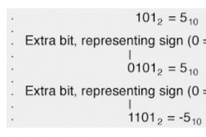
Subtraction can be transformed into addition by treating the subtrahend as a negative value; for example, 7 − 5 becomes 7 + (−5). Once positive binary representation is mastered, the next step is to encode negative numbers so that subtraction can be performed using the same addition routine. In deci
Industrial Technology

Maximize ROI: Avoid Common Pitfalls With Your Cleaning Robot

Carbon Fiber & Additive Manufacturing Elevate Performance of Miro Buroni’s Pleko Spike Shoes

From Navy Mechanic to Pioneer: Swanton Welding’s Founding Story

Threaded Inserts via Heat Staking & Ultrasonic Welding – Precision Solutions for Molded Parts
