Industrial manufacturing
Industrial Technology

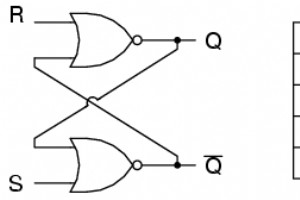
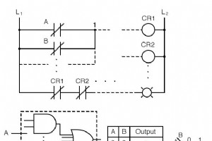
A bistable multivibrator has two stable states, hence the prefix bi. One state is called set and the other reset. The most basic form of this device is the set‑reset (S‑R) latch. To build an S‑R latch, two NOR gates are wired so that each gate’s output feeds back to the other gate’s input, creating
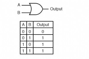
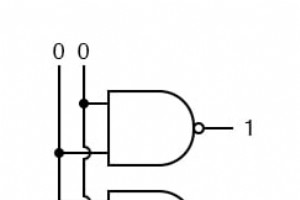
In conventional combinational logic, each input combination produces a unique, predictable output. For example, an OR gate follows the truth table shown below: With four possible input states (0‑0, 0‑1, 1‑0, 1‑1), the output is always unambiguous. Whether a circuit contains a single g
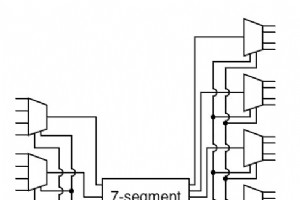
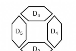
In this practical example, we demonstrate how to build a four‑digit 7‑segment display that accepts a 16‑bit binary input—representing a decimal number—and drives the display using a single binary‑to‑7‑segment encoder. The design showcases the power of combinational logic, demultiplexing, and modular

A multiplexer, commonly abbreviated as MUX, is a digital switching device that routes one of many input signals to a single output line based on selector inputs. The standard schematic symbol for a multiplexer is illustrated below: Below is the truth table for a classic 2‑to‑1 multiplexer. The sele
A demultiplexer, often shortened to dmux, is a fundamental digital logic component that takes a single input line and directs the signal to one of several output lines based on select inputs. Unlike a decoder, which maps input codes to one active output, a demultiplexer actively routes the input dat
What Is an Encoder? An encoder is a combinational circuit that converts a set of input signals into a binary‑coded output. It is the logical inverse of a decoder. In practice, encoders are used to reduce the number of signals required to represent a set of inputs, which simplifies downstream proce
A decoder is a logic circuit that transforms a binary code into a set of output signals. While it performs the inverse operation of an encoder, decoders are typically simpler to design and provide a solid foundation for learning about binary logic circuits. Types of Decoders Line Decoder The most co
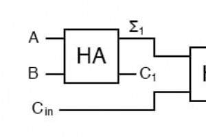
When you add more than two binary digits, a single half‑adder is no longer sufficient. The traditional approach—creating a truth table for each new width—is accurate but slow. A full adder overcomes this by handling a third input, the carry‑in, allowing the design to scale quickly and reliably. Cons
In digital electronics, the half‑adder is the simplest combinational circuit that adds two single‑bit binary numbers. It produces two outputs: the low‑order sum (Σ) and the high‑order carry out (C_{out}). Understanding this device is foundational for designing more complex arithmetic units suc
The term "combinational" originates from mathematics, where a combination is an unordered set. In this context, the order of input changes does not affect the circuit’s output. Consequently, a combinational logic circuit delivers the same result regardless of the sequence in which its inpu
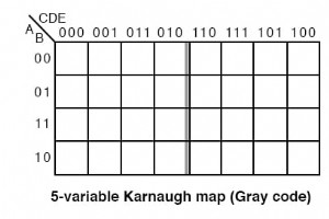
As combinational logic grows, the size of the Karnaugh map expands. Knowing when a 5‑ or 6‑variable map is appropriate—and how to interpret and group its cells—can cut logic usage dramatically in FPGA and ASIC designs. Altera (now part of Intel) examined thousands of customer designs to understand t
Up to now, we’ve tackled logic‑reduction problems where every input combination is fully specified. A 3‑variable truth table, for example, contains 2^3 = 8 entries and the corresponding Karnaugh map is fully populated. In many real‑world applications, however, we do not need to define every possible
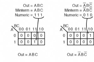
This section clarifies the notation commonly used to list minterms and maxterms in Karnaugh maps. It offers no new theory but provides a concise, practical reference. Terminology for Minterms The Greek letter Σ (sigma) denotes a sum, and the lowercase “m” specifies minterms. Together, Σ
In digital logic design, we often simplify Boolean expressions to reduce gate count and improve performance. While most textbooks focus on Sum‑of‑Products (SOP) solutions, every SOP has a complementary Product‑of‑Sums (POS) form that can be more advantageous for certain logic families. Understandin
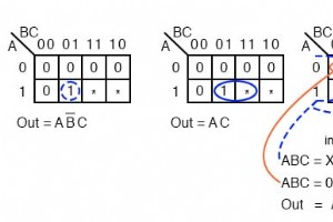
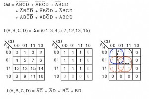
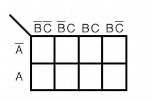
Once you understand Gray code sequencing, extending a 3‑variable Karnaugh map to 4 variables is straightforward: copy the column sequence of the 3‑variable map to the left side of the 4‑variable grid. See the illustration below. Reductions of 4‑Variable K‑Maps The following examples demonstr
While Boolean algebra can simplify logic expressions swiftly, real‑world problems often demand handling larger truth tables. Karnaugh maps provide a visual, systematic approach to reduce complex logic functions efficiently. In this article we walk through contrived examples that illustrate the key t
Who Created the Karnaugh Map?Maurice Karnaugh, a telecommunications engineer at Bell Labs, introduced the Karnaugh map in 1953 while designing digital logic for telephone switching circuits.Why Use a Karnaugh Map?The Karnaugh map is a visual tool that reduces complex Boolean functions faster and mor
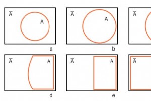
Starting with circle A in a rectangular A’ universe in figure (a) below, we morph a Venn diagram into almost a Karnaugh map. We expand circle A at (b) and (c), conform to the rectangular A’ universe at (d), and change A to a rectangle at (e). Anything left outside of A i
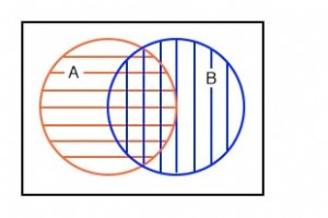
The fourth illustration shows set A partially overlapping set B. We first consider the full hatched area that represents the union of both sets, and later isolate the intersection. Below left, a red horizontal hatched region denotes A; a blue vertical hatched region denotes B. When we aggregate all
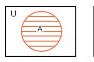
Mathematicians use Venn diagrams to show the logical relationships of sets (collections of objects) to one another. Perhaps you have already seen Venn diagrams in your algebra or other mathematics studies. If you have, you may remember overlapping circles and the union and intersection of sets. We
Industrial Technology